14 - 5
Dismantling
Refer to the illustrations on pages 14 - 1 to 14 - 3 and the
component list on page 14 - 4. In the following procedures,
the part numbers in bold type (e.g. 71) correspond with the
numbers on the illustrations.
Before attempting to dismantle the hydraulic pump, drain all
oil, blank all inlet and outlet ports and wash the outer
surfaces with a suitable solvent to remove all dirt and dust.
Dry using compressed air.
Make different alignment marks across each sub-assembly
joint face as an aid to assembly.
The cylinder block assemblies, servo pump, relief valve and
proportional pressure reduction valve must be replaced as
complete assemblies.
The following procedures show a complete strip down, but,
unless absolutely necessary, avoid disturbing or dismantling
the control elements of the pump, i.e. those retained by
covers 30, 52 and 53 and by plugs 31 and 35. Any
interference with setting screws will affect pump output
control, necessitating precision re-setting on the bench.
The pump/regulator unit contains two pressure pumps, P1
and P2. Take care not to get the parts from one mixed in
with parts from the other.
During dismantling, record the number and dimensions of
shims. Take care to reassemble in the same manner.
Section E Hydraulics
9803/6410
Section E
14 - 5
Issue 1
Hydraulic Pump/Regulator
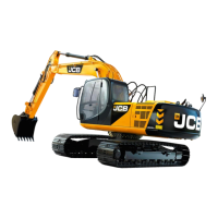
Note: Protect the clamping faces when supporting the pump
housing in the vice.
1 Support pump housing 1 in a vice, clamped across the
inlet and outlet port flanges. Unscrew the four socket
head bolts 71 and remove mounting flange 61.
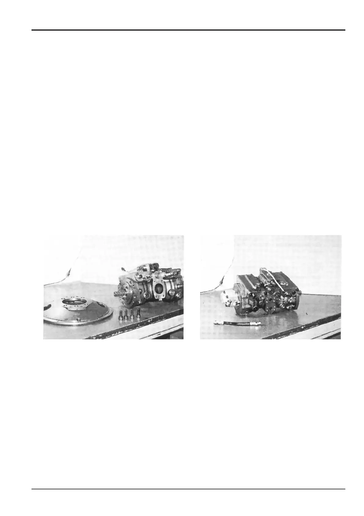
2 Remove hose 59.
 Loading...