8 - 1
Section F Transmission
9803/6410
Section F
8 - 1
Issue 1
Traction Motor
Dismantling
Refer to the following pages:
JS130 7 - 1 and 7 - 2 (illustrations)
7 - 4 to 7 - 5 (component list)
JS160 7 - 6 and 7 - 7 (illustrations)
7 - 9 to 7 - 10 (component list)
In the following procedures, the part numbers in bold type
(e.g. 170) correspond with the numbers on the illustrations.
Before attempting to dismantle the traction motor, drain all
oil, blank all inlet and outlet ports and wash the outer
surfaces with a suitable solvent to remove all dirt and dust.
Dry using compressed air.
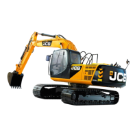
1 Loosen, but do not remove plug 204 and the two
sleeves 202 in relief valve body 212.
2 Unscrew the four socket head bolts 170 and remove
relief valve body 212 from rear flange 101. Remove the
two ‘O’-rings 156 from the rear flange and discard.
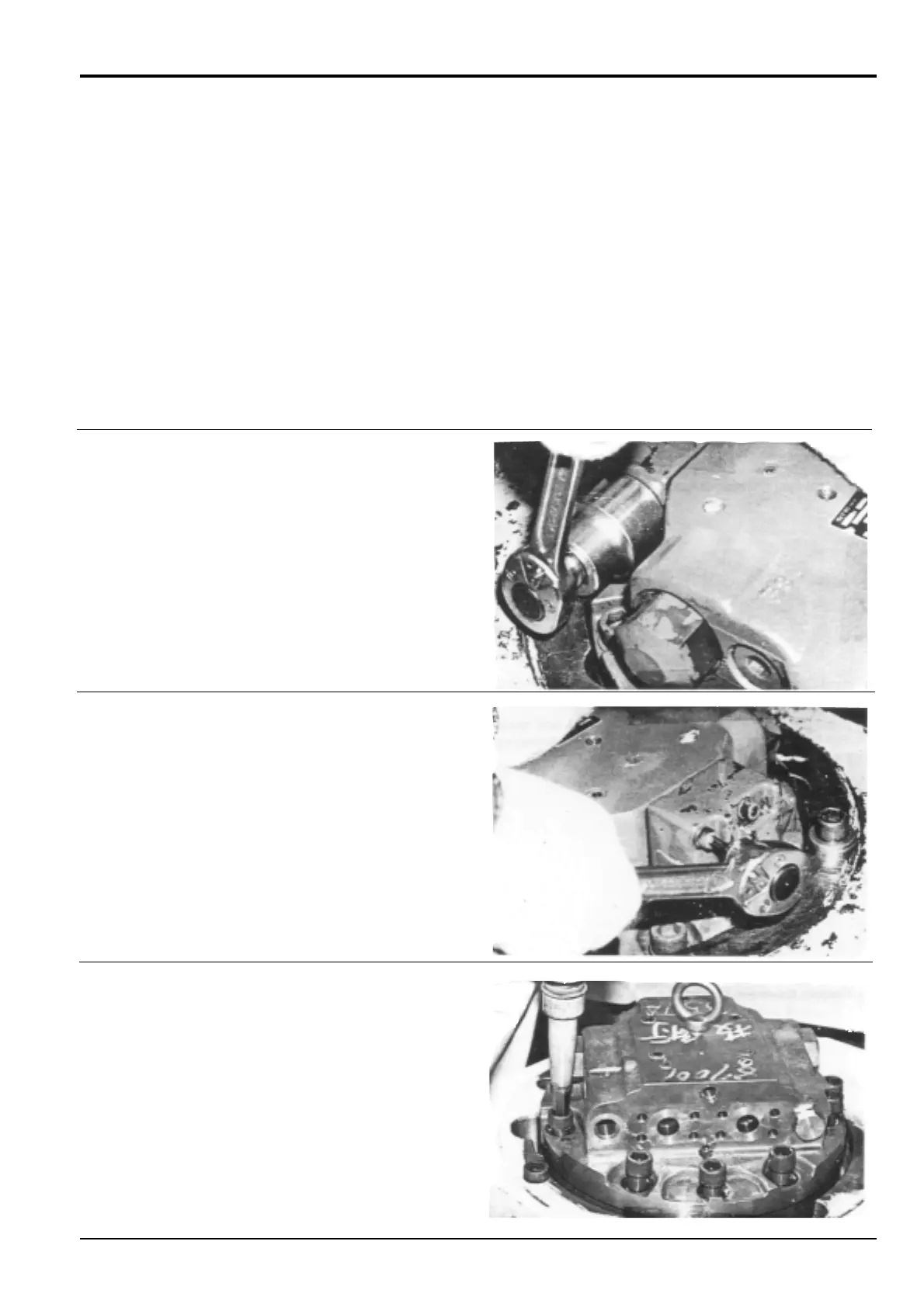
3 Remove nine hexagonal socket bolts 143.
Make different alignment marks across each sub assembly
joint faces as an aid to assembly.
The cylinder block assemblies, servo pump, relief valve and
proportional pressure reduction valve must be renewed as
complete assemblies.
During dismantling, record the number and dimensions of
shims. Take care to reassemble in the same manner.
 Loading...