Routine Maintenance
Forks
160 160
9811/5700-7
Installation
Note: Make sure that you install the correct type of fork for
the type of carriage fitted. Do not attempt to fit the incorrect
forks.
1 Park the machine on solid level ground. Make sure
the park brake is engaged and select neutral.
2 Position the fork so that the upper hook D can engage
the top of the carriage E. K
Fig 126. ( T 159)
3 Raise the carriage to locate the bottom hook B in the
lower removal notch C. K Fig 126. ( T 159)
4 Make sure each fork has engaged the carriage at the
top and bottom positions. Slide each fork along the
carriage, away from the lower removal notch C.
K
Fig 126. ( T 159)
!MWARNING
If the fork/locking pin is not fully engaged, the fork
could become unintentionally disengeged.
12-6-1-13
5 Re-engage locking pins A into the required notches.
6 Install the locking clamp X onto the bottom of the
carriage. K
Fig 126. ( T 159).
K
Industrial Carriage Fork Adjustment ( T 66)
Important: The locking clamp must be fastened to the
carriage at all times during machine operation.
Bar Carriage Forks
Removal
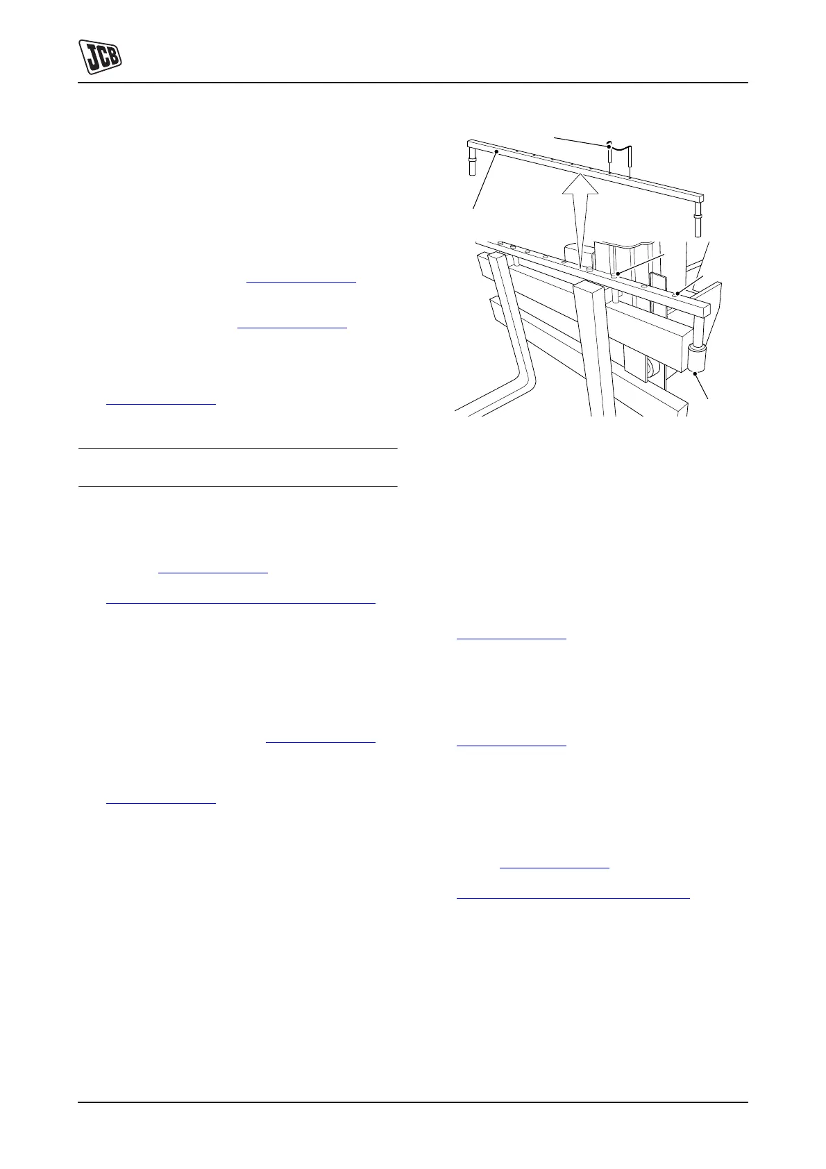
1 Remove the location pins A. K Fig 127. ( T 160)
2 Release the retaining clips G from the bar securing
pins and remove the bar H from the carriage.
K
Fig 127. ( T 160)
3 Using suitable lifting equipment, support the fork and
slide it to the end of the carriage.
4 Use the lifting equipment, remove the fork from the
carriage.
T069180-2
Fig 127. Bar Type Carriage
Installation
Note: Make sure that you install the correct type of fork for
the type of carriage fitted. Do not attempt to fit the incorrect
forks.
1 Park the machine on solid level ground. Make sure
the park brake is engaged and select neutral.
2 Position the fork so that the upper hook D and bottom
hook D can engage the end of the carriage.
K
Fig 126. ( T 159)
3 Using the lifting equipment, support the fork and slide
it along the carriage.
4 Install the bar H onto the top of the carriage and
secure into position with retaining clips G.
K
Fig 127. ( T 160)
5 Make sure that each fork has engaged the carriage
correctly at the top and bottom positions.
6 Refit the two pairs of retaining pins A using one pair
for each fork. Make sure that each pin drops freely
into place and that each pair of pins is positioned as
shown. K
Fig 127. ( T 160).
K
Bar Carriage Fork Adjustment ( T 66)
G
H
A
A
H
 Loading...