Operation
Cab Layout
33 33
9811/5700-7
Component Key
Fig 20.
T011630-4
Fig 21.
1 K
Steering Wheel ( T 34).
2 K
Gear Lever ( T 35).
3 K
Starter Switch ( T 39).
4 K
Park Brake Lever ( T 34).
5 K
Accelerator Pedal ( T 34).
6 K
Foot Brake Pedal ( T 34).
7 K
Transmission Dump (Disconnect)
Switch ( T 35).
8 K
Operating Levers ( T 44).
9 K
Side Console ( T 36).
10 K
Instrument Panel ( T 41).
11 K
Multi-Purpose Steering Column
Switch ( T 38).
12 K
Heater Controls ( T 43).
13
K Auxiliary Power Socket ( T 40) (if fitted)
(1)
(1) Supply for 12 Volt accessories (Maximum 10 Amp).
14 K
Transmission Lever ( T 34).
15 K
Horn ( T 35).
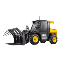
16 K
Air Conditioning Controls ( T 43).
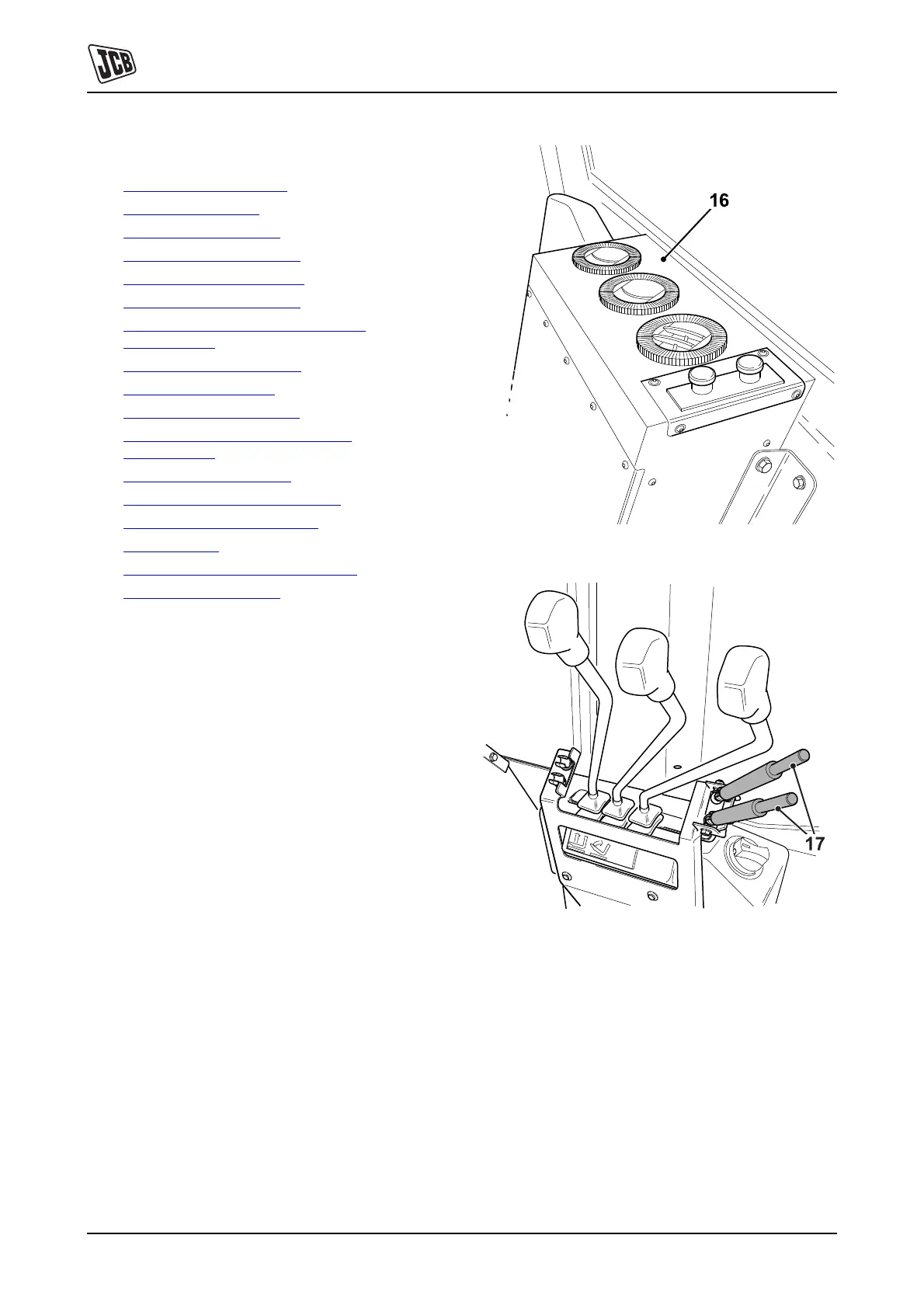
17 K
Control Locks ( T 48).
 Loading...