3.1.5 Preset channel buttons
These buttons are used to recall already stored channels.
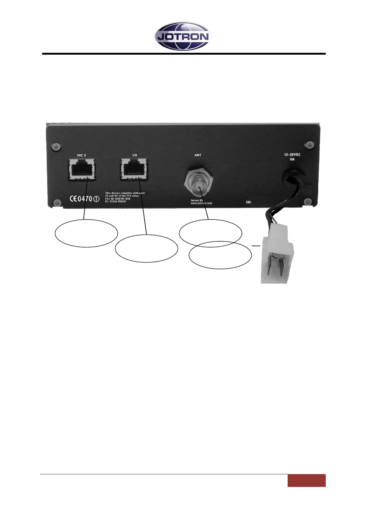
3.2 Transceiver, rear connections
Figure 3.2-1, TR-810 transceiver unit, rear view
3.2.1 Antenna connector (50 ohm N)
Interface to the antenna cable for the transceiver Connector (50 ohm BNC).
This connector is connected to the antenna switch internally in the transceiver unit.
3.2.2 DC Connector
The DC wires are connected to the external DC supply (+12V to + 28V ±10%), or directly to
the cars battery via a separate external fuse.
The Red wire is the positive connection and Black wire is the negative.
A thin Green wire is together with the DC input wires. This wire can be connected to +
voltage through the ignition key, to automatically turn the TR-810 off when the ignition is
turned off.
To ignore this possibility, this wire has to be connected to a constant + voltage.
84417_O&I_TR-810_G Functional description
Page 3-3
 Loading...