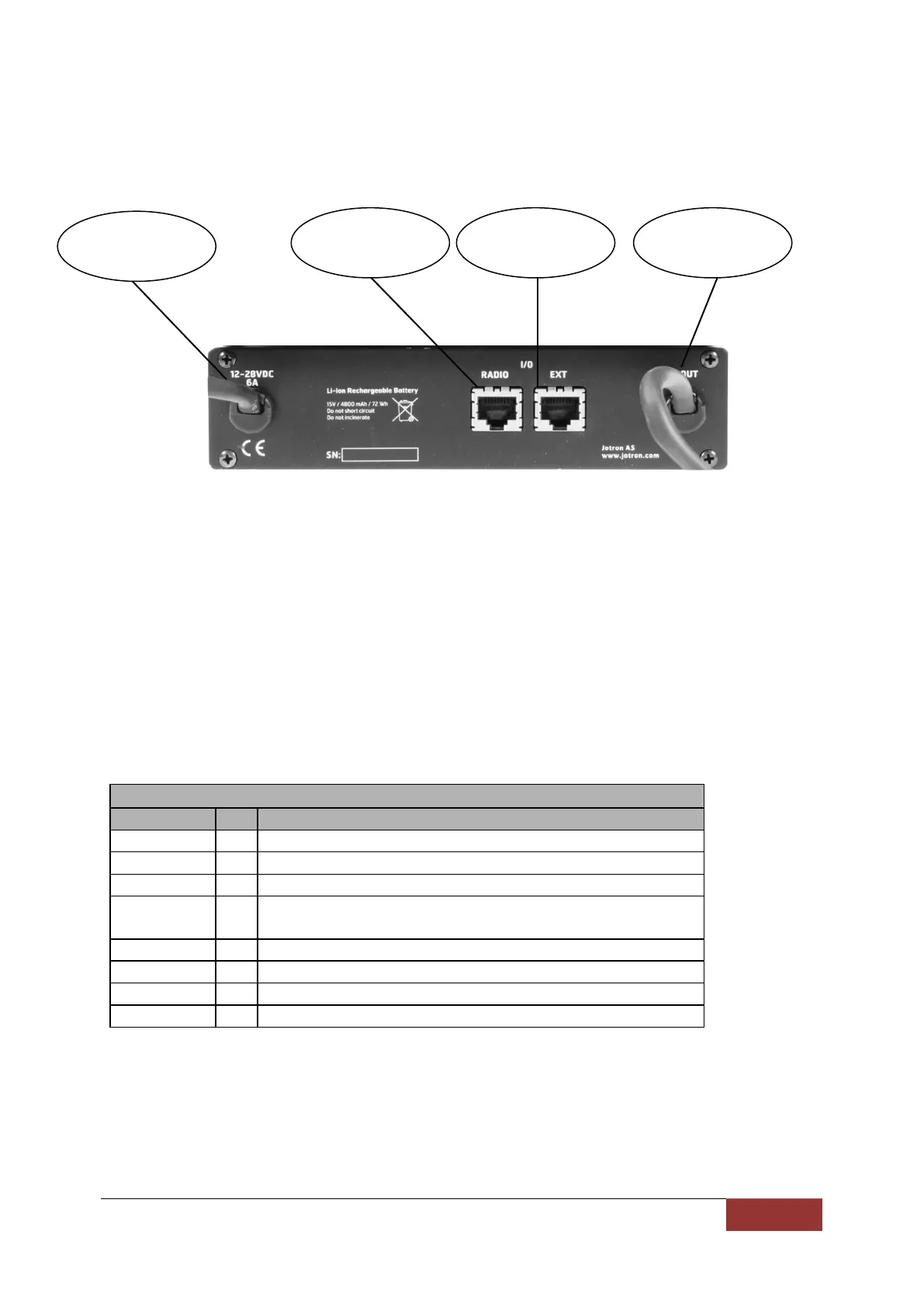
7.3 Rear connection
7.3.1 Dc input
Connect to the external DC supply (+12V to + 28V ±10%)
(Same pin. Configuration as on the TR-810 DC INPUT)
7.3.2 Radio connector
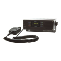
Connect to TR-810 with 1:1 cable (RJ45)
7.3.3 Ext connector
Contains I/O signals from both the TR-810 and the Battery Backup Unit (RJ45)
To tape recorder etc. 600Ω unbalanced
Grounding this pin will force the transmitter to
1W power (Gas alarm)
Triggered by loss of DC input. Dry relay makes contact to pin. 7
Bypass from Radio connector pin. 6.
Triggered by loss of DC input. Dry relay makes contact to pin. 5
7.3.4 Dc output
Connect to DC INPUT on the TR-810 (approx 15V)
(Same pin. Configuration as on the TR-810 DC INPUT)
84417_O&I_TR-810_E Battery Backup Unit Page 7-5
 Loading...