EasyManua.ls Logo

jotron TR-810 User Manual

jotron TR-810
50 pages
To Next Page IconTo Next Page
To Previous Page IconTo Previous Page
Page #18 background imageLoading...
Page #18 background image
4.4 Installation of TR-810
4.4.1 Split installation parts
Figure 4.4.1-1 shows some extra parts used for split installation. The TR-810 can be mounted
as a Mobile radio, Desk top or flush mounted into a horizontal or vertical area. The front
module can be mounted separately away from the transceiver unit using an extension cable
and a mounting plate or a bracket.
Item
number
Document
number
Title
Quantity
1
82767
TRANSCEIVER UNIT W/ DESKTOP BRACKET
1
2
84082
FRONT COVER PLATE W/FLANGE
1
3
84416
CONSOLE MOUNTING PLATE FRONT MODULE
1
4
84414
BRACKET FRONT MODULE
1
5
82276
DIN912-CYL HEAD UNBRAKO M4X10
2
Figure 4.4.1-1, Examples of various parts used for split installation
84417_O&I_TR-810_G Installation
Page 4-2
Question and Answer IconNeed help?

Do you have a question about the jotron TR-810 and is the answer not in the manual?

jotron TR-810 Specifications

General IconGeneral
Brandjotron
ModelTR-810
CategoryRadio
LanguageEnglish

Summary

Approvals

Standards

List of Abbreviations and Definitions

Amendment Record

Safety Instructions

Precautions

Safety Precautions

Warning Statement

Modification Warning Statement

Digital Device Statement

Introduction

Models Covered by this Manual

Lists the TR-810 models and their part numbers.

Transceiver Layout

Applications

Technical Specifications

General Specification TR-810

Comprehensive general specifications for the TR-810 model.

Functional Description

Front Module Controls

Details the controls and indicators on the front panel.

Display Indicators

Explains the information shown on the display and status icons.

Navigation Controls

Power Button Operation

Front Mic/Headset Connector

Preset Channel Buttons

Rear Connections

Antenna Connector

Details the antenna connector type and its function.

DC Connector

Explains the DC connector for power supply and ignition sense.

I/O Connector (RJ45)

MIC II Connector (RJ45)

Installation

Compass Safe Distance

Specifies the minimum safe distance from compasses.

Installation Introduction

Overview of the installation procedures and recommendations.

Initial Inspection

Steps for inspecting the equipment upon receipt.

TR-810 Installation

Split Installation Parts

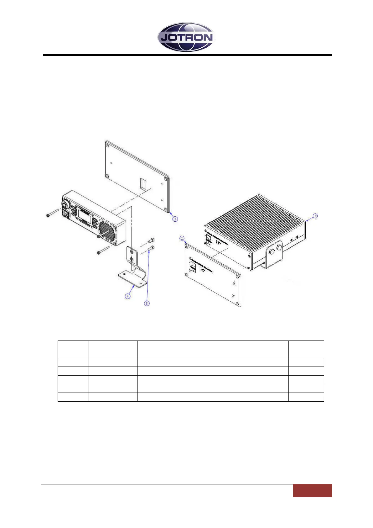
Lists parts used for split installation of the TR-810.

TR-810 Dimensions

Desktop Mounting

Flush Mounting

Antenna Connectors

DC Connection

Remote Signals

Operating Instructions

Operating Instructions Introduction

Overview of parameter setting and user levels.

Frequency Setting

Restricted Access Level Menu

Non-Restricted Access Level Menu

Channel Setup Menu

Configuration Menus

RX Settings

Parameters for external speaker, squelch, AAGC, and noise blanking.

TX Settings

Parameters for TX power, timeout, and modulation.

Channel Setup Menu Options

Audio Settings

BITE Information Menus

Error Conditions and Corrective Actions

Battery Backup Unit

Last Resort Radio Application

Use of BU-872 for maintaining communication during power failure.

ManPortable Application

Use of BU-872 for portable operation with antenna and carry bag.

Battery Backup Unit Technical Specifications

Battery Backup Unit Front Panel

LED Indicators

On, Charge, and Alarm LEDs indicate status and faults.

Power Meter and Test Button

Power meter shows battery capacity; Test button activates it.

DC Input Connection

Radio Connector

External Connector (I/O)

DC Output Connection

TR-810 Battery Indicator

TR-810 Man Portable Dimensions

TR-810 Man Portable Assembly

TR-810 Last Resort Dimensions

Battery Maintenance

Maintenance Charge Procedure

How to perform a maintenance charge on the batteries.

Balancing Procedure

Steps for performing a battery balancing procedure.

Balancing Procedure Instructions

BU-872 Battery Storage Recommendations

Battery Storage Temperature

Battery Storage Conditions

Battery De-storage Conditions

Related product manuals