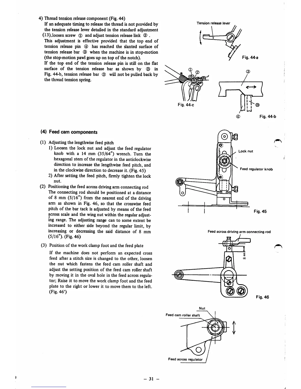
4) Thread tension releasecomponent (Fig.44)
If an adequate timing to release the thread is not provided by
the tension release lever detailed in the standard adjustment
(13),loosen
screw
® and
adjust
tension
release
link
(D
.
This adjustment is effective provided that the top end
of
tension release pin ® has reached
the
slanted surface
of
tension release bar (D when the machine is in stop-motion
(the stop-motion pawlgoesup on top of the notch).
If the top end
of
the tension
release
pin is still on the flat
surface of the tension release bar as shown by
(B)
in
Fig. 44-b, tension release bar (D will not be pulled back by
the thread tension spring.
(4) Feed cam components
(1)
Adjusting
the
lengthwise
feed
pitch
1)
Loosen
the lock nut and
adjust
the
feed
regulator
knob with a 14 mm (35/64")
wrench.
Turn the
hexagonal stem of the regulator in the anticlockwise
direction to
increase
the
lengthwise
feed
pitch, and
in the
clockwise
direction to
decrease
it. (Fig.45)
2) After setting the
feed
pitch,
firmly
tightenthe lock
nut.
(2)
Positioning
the
feed
across
driving
arm
connecting
rod
The connecting rod should be positioned at a distance
of 8
mm
(5/16")
from
the
nearest
end
of
the
driving
arm as shown in Fig.
46,
so
that
the
crosswise feed
pitch of the bar tack is adjusted by means of the feed
across
scale
and the
wing
nut
within
the
regular
adjust
ing range. The adjusting range can to some extent be
increased
to either
side
beyond the
regular
limit, by
increasing or decreasing the said distance of 8 mm
(5/16").
(Fig.
46)
(3) Positionof the work clamp foot and the feed plate
If the machine does not perform an expected cross
feed after a stitch size is changed to the other, loosen
the
nut
which
fastens
the
feed
cam
roller
shaft
and
adjust the setting position
of
the
feed cam roller shaft
by moving it in the oval hole in the feed acrossregula
tor; Raise it to move the work clamp foot and the feed
plate to the right or lower it to move them to the left.
(Fig.
46')
-
31
-
Tension
release
lever
•
Fig.
44-c
Nut
Feed
cam
roller
shaft
O
Feed
across
regulator
Fig.
44-a
Fig.
44-b
Lock
nut
Feed
regulator
knob
Fig.
45
Feed across driving
arm
connecting
rod
I'.!
Fig.
46
 Loading...