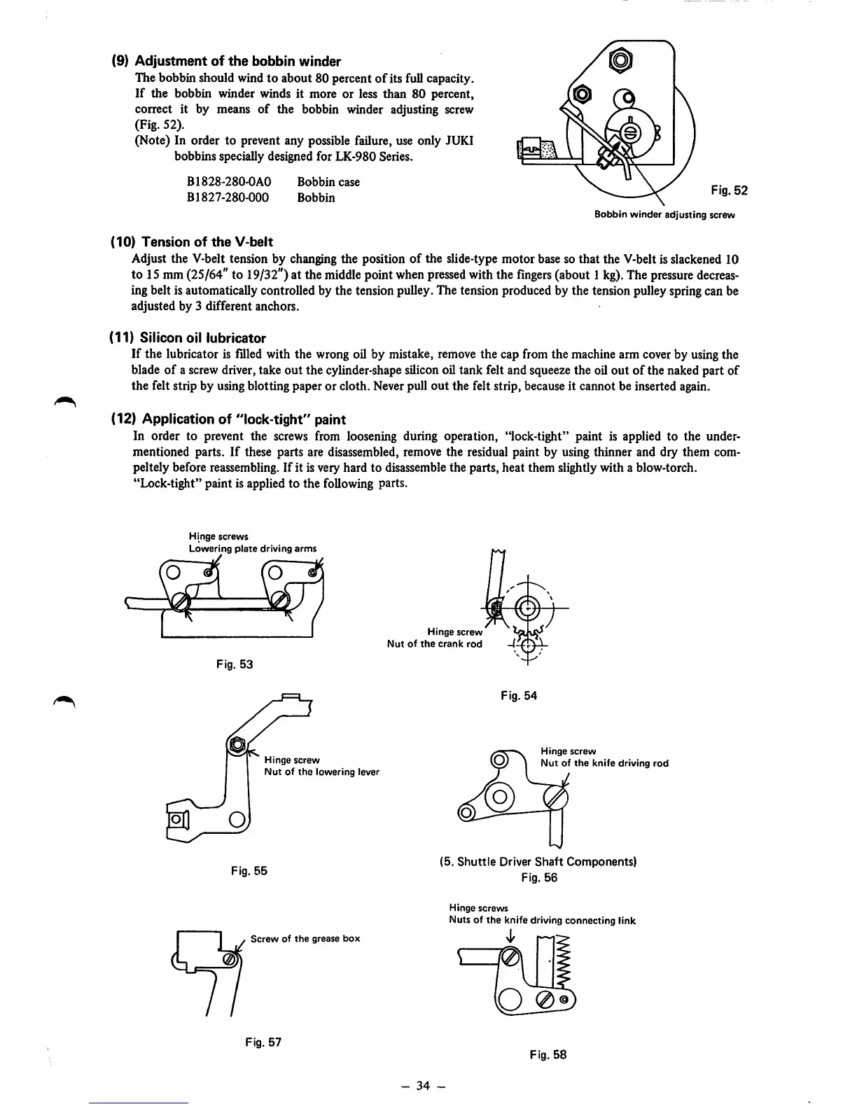
(9)
Adjustment
of
the
bobbin
winder
The bobbin should wind to about 80 percent
of
its full capacity.
If
the bobbin winder winds it more or less than 80 percent,
correct it by means
of
the bobbin winder adjusting screw
(Fig. 52).
(Note) In order to prevent any possible failure, use only JUKI
bobbins specially designed for LK-980 Series.
B1828-280-0A0
B1827-280-000
Bobbin
case
Bobbin
Fig.
52
Bobbin
winder
adjusting
screw
(10)
Tension
of
the
V-belt
Adjust the V-belt tension by changing the position
of
the slide-type motor base so
that
the V-belt is slackened 10
to 15mm
(25/64"
to 19/32") at the
middle
point
when
pressed
withthe
fingers
(about1
kg).
The
pressure
decreas
ing belt is automatically controlled by the tension pulley. The tension produced by the tension pulley spring can be
adjusted by 3 different anchors.
(11)
Silicon
oil
lubricator
If the lubricator is filled with the wrong oil by mistake, remove the cap from the machine arm cover by using the
blade
of
a screw driver, take out the cylinder-shape silicon oil tank felt and squeeze the oil out
of
the naked part of
the felt strip by using blotting paper or cloth. Neverpull out the felt strip, becauseit cannot be inserted again.
(12) Application of "lock-tight" paint
In order to prevent the screws from loosening during operation, "lock-tight" paint is applied to the under
mentioned parts. If these parts are disassembled, remove the residual paint by using thinner and dry them com-
peltely before reassembling. If it is very hard to disassemble the parts, heat them slightly with a blow-torch.
"Lock-tight" paint is applied to
the
following parts.
Hinge
screws
Lowering
plate
driving
arms
Fig.
53
Hinge
screw
Nut
of
the
lowering
lever
Fig.
55
Screw
of
the
grease
box
Fig.
57
Hinge
screw
Nut
of
the
crank
rod
Fig.
54
Hinge
screw
Nut
of
the
knife
driving
rod
(5.
Shuttle
Driver
Shaft
Components)
Fig.
56
Hinge
screws
Nuts of
the
knife driving
connecting
link
Fig.
58
-
34
-
 Loading...