− 39 −
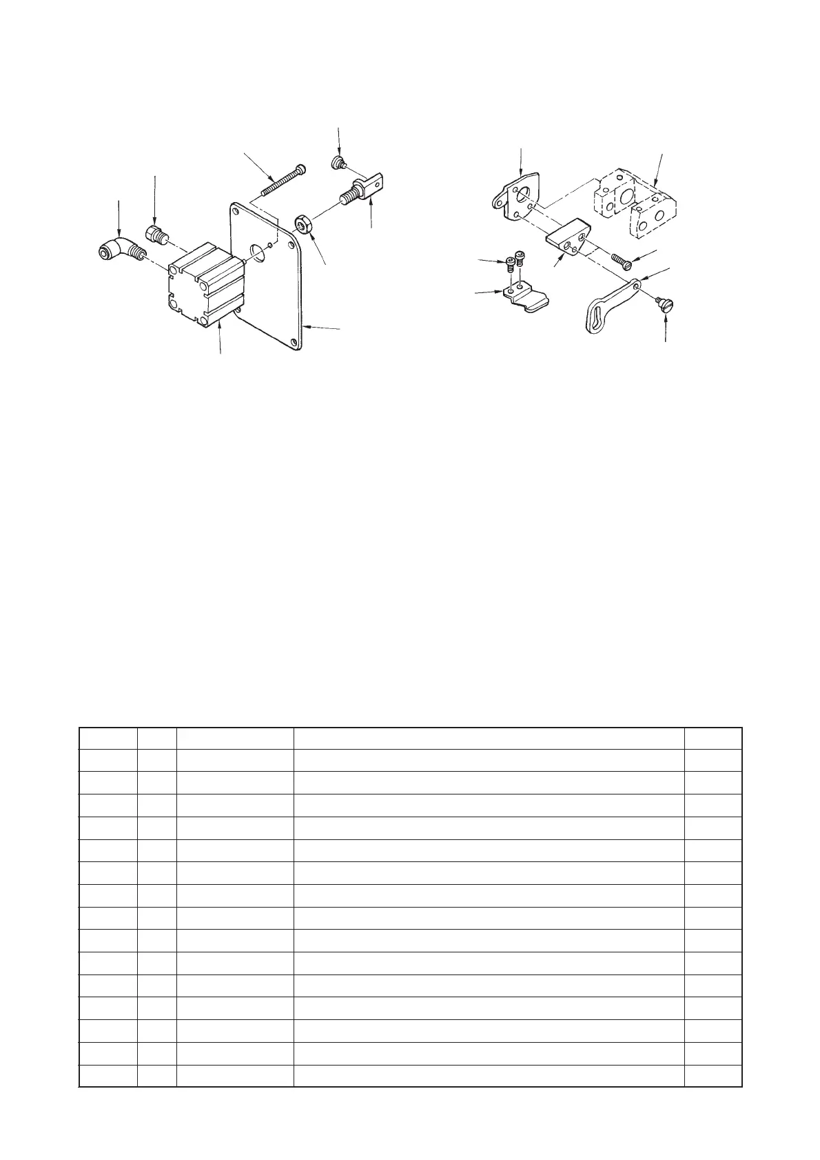
(3) DL device (LS-1342)
1) Installing the DL device
2) Installin procedure of the DL device after set-up of the machine
1. Remove the window plate E located on the anti-operator’s side of the machine arm.
2. Attach elbow 2, muffler 3, cylinder connecting screw 4, alternate vertical link hinge screw 5 and nut
6 to jig cylinder 1.
3. Attach the jig cylinder 1 which has been assembled at the above step 2. to window plate F 7 and
tighten it with jig cylinder setscrew 8.
4. Remove the top feed stopper plate A attached to alternate vertical change base !6 and attach top feed
stopper plate B 9.
5. Tighten alternate vertical link spacer !0 to top feed stopper plate B 9 with setscrew !1 and tighten
alternate vertical link !2 with hinge screw !3.
6. Tighten alternate vertical link support !4 to the machine arm with setscrews !5.
7. When installing window plate F 7, enter alternate vertical link hinge screw 5 to the hole of alternate
vertical link !2 and attach it to the machine arm.
8. Install the pneumatic device components (asm.).
9. Install the 5-step switch (asm.) and connect the relay cord with it.
10.Insert the air hose and check the operation.
™ When actuating DL, the amount of the alternate vertical movement becomes maximum and the
walking foot goes up.
◎ DL device components
Part No.
PA320200101
PJ304065102
PX015101000
21438403
SD0600403TP
NM6080721SE
21437207
SM6044002TP
21438106
21438601
SS6111610SP
21438502
SD0600452TP
21438700
SS4110815SP
No.
1
2
3
4
5
6
7
8
9
!0
!1
!2
!3
!4
!5
Note Name of part
Jig cylinder
Elbow
Muffler
Cylinder connecting screw
Alternate vertical link hinge screw
Nut
Window plate F
Jig cylinder setscrew
Top feed stopper plate B
Alternate vertical link spacer
Setscrew
Alternate vertical link
Hinge screw
Alternate vertical link support
Setscrew
Q’ty
1
1
1
1
1
1
1
2
1
1
2
1
1
1
2
1
2
3
4
5
6
7
8
9
!0
!1
!2
!3
!4
!5
!6
 Loading...