−49 −
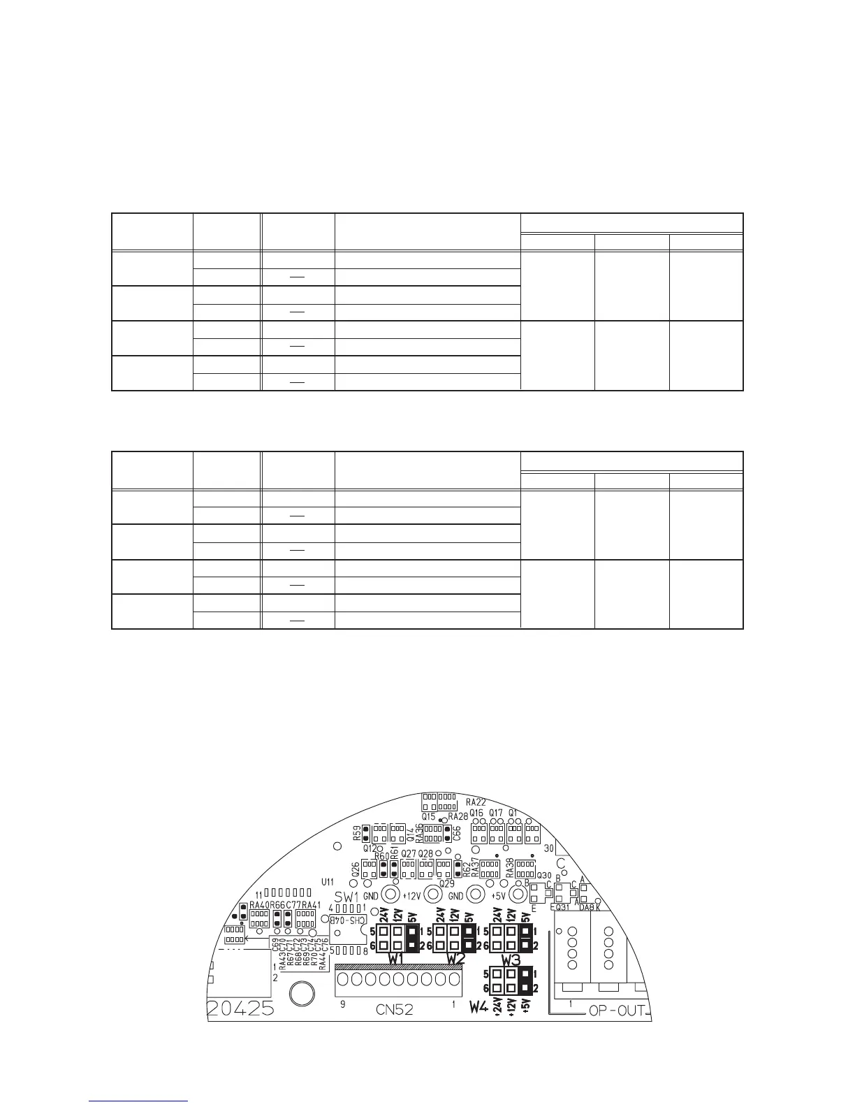
(6) Setting procedure of optional power and setting procedure of jumper
for input changeover
Lists below are those of setting procedure of power voltage of optional connectors.
By setting respective jumper wires, +5V, +12V and +24V can be used.
* +5V has been set at the time of delivery from factory.
1. Input connector
2. Output connector
Caution when using optional power
1) Note that the power for optional is 0.6A in total when IPOP p.c.b. is not used,
and that the power for optional should not exceed 0.4A when IPOP p.c.b. is mounted.
7-segment
display No.
Vcc4
Vcc4
Vcc3
Vcc3
Connector No.
CN51-1
CN51-2
CN51-3
CN51-4
Pin No.
1
4
1
4
1
4
1
4
Function
Power voltage selected with W4
GND
Power voltage selected with W4
GND
Power voltage selected with W3
GND
Power voltage selected with W3
GND
Jumper for optional power selection
+5V
W4 1-2
W3 1-2
+12V
W4 3-4
W3 3-4
+24V
W4 5-6
W3 5-6
7-segment
display No.
Vcc1
Vcc1
Vcc2
Vcc2
Connector No.
CN50-1
CN50-2
CN50-3
CN50-4
Pin No.
1
4
1
4
1
4
1
4
Function
Power voltage selected with W1
GND
Power voltage selected with W1
GND
Power voltage selected with W2
GND
Power voltage selected with W2
GND
Jumper for optional power selection
+5V
W1 1-2
W2 1-2
+12V
W1 3-4
W2 3-4
+24V
W1 5-6
W2 5-6
3. Layout diagram of jumper for optional changeover of power

 Loading...