3 Device description
3.1 Function
The device converts the DC voltage generated by the PV modules into AC voltage and feeds it into
the grid. The starting procedure begins when there is sufficient sunlight and a specific minimum volt-
age is present in the device. The feed-in process begins once the PV generator has passed the insu-
lation test and the grid parameters are within the requirements imposed by the grid operator for a spe-
cific monitoring time. If, as it gets dark, the voltage drops below the minimum voltage value, feed-in
mode ends and the device switches off.
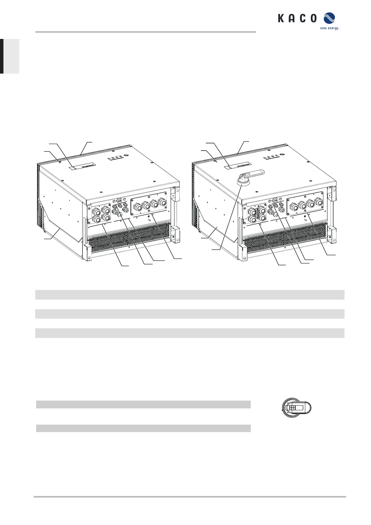
3.2 Structure of the device
Fig.3: Device diagram - S version
Fig.4: Device diagram - XL version
Key
1 Housing 6 Interface / cable feed-through
2 Cover 7 Communication - button / USB port
3 Status indicator 8 DC connection / cable feed-through
4 Upper cover 9 DC isolator switch (not present in S version)
5 AC connection / cable feed-through
3.2.1 Mechanical components
DC isolator switch (not present in S version)
The DC isolator switch is located on the housing door. of the device. The DC isolator switch is used to
disconnect the device from the PV generator in order to carry out service.
Disconnecting the device from the PV generator
F Switch the DC isolator switches from 1 (ON) to 0 (OFF).
Connecting the device to the PV generator
F Switch the DC isolator switches from 0 (OFF) to 1 (ON).
Fig.5: DC isolator switch
3.2.2 Electrical functions
A potential-free relay contact is integrated into the device. Use this contact for one of the following
functions:
3 | Device description Manual
KACO blueplanet 87.0 TL3 KACO blueplanet 92.0 TL3 KACO blueplanet 105 TL3 KACO blueplanet 110 TL3
KACO blueplanet 125 TL3 KACO blueplanet 137 TL3 KACO blueplanet 150 TL3 KACO blueplanet 155 TL3
KACO blueplanet 165 TL3
Page 10
EN-US
 Loading...