Attach the DRM 0 safety label
According to AS/NZS 4777.2:2015, in Australia PV devices are marked that
support the "Mode 0" remote control command.
1. Attach the supplied safety sticker next to the name plate on the device
housing where it is clearly visible.
2. Please note the Powador-protect application note in the download area
on our homepage. Here you will find the corresponding "Demand Re-
sponse Modes" listed in the chapter "Referencing for power control".
Fig.42: Sticker DRM 0 for Australia
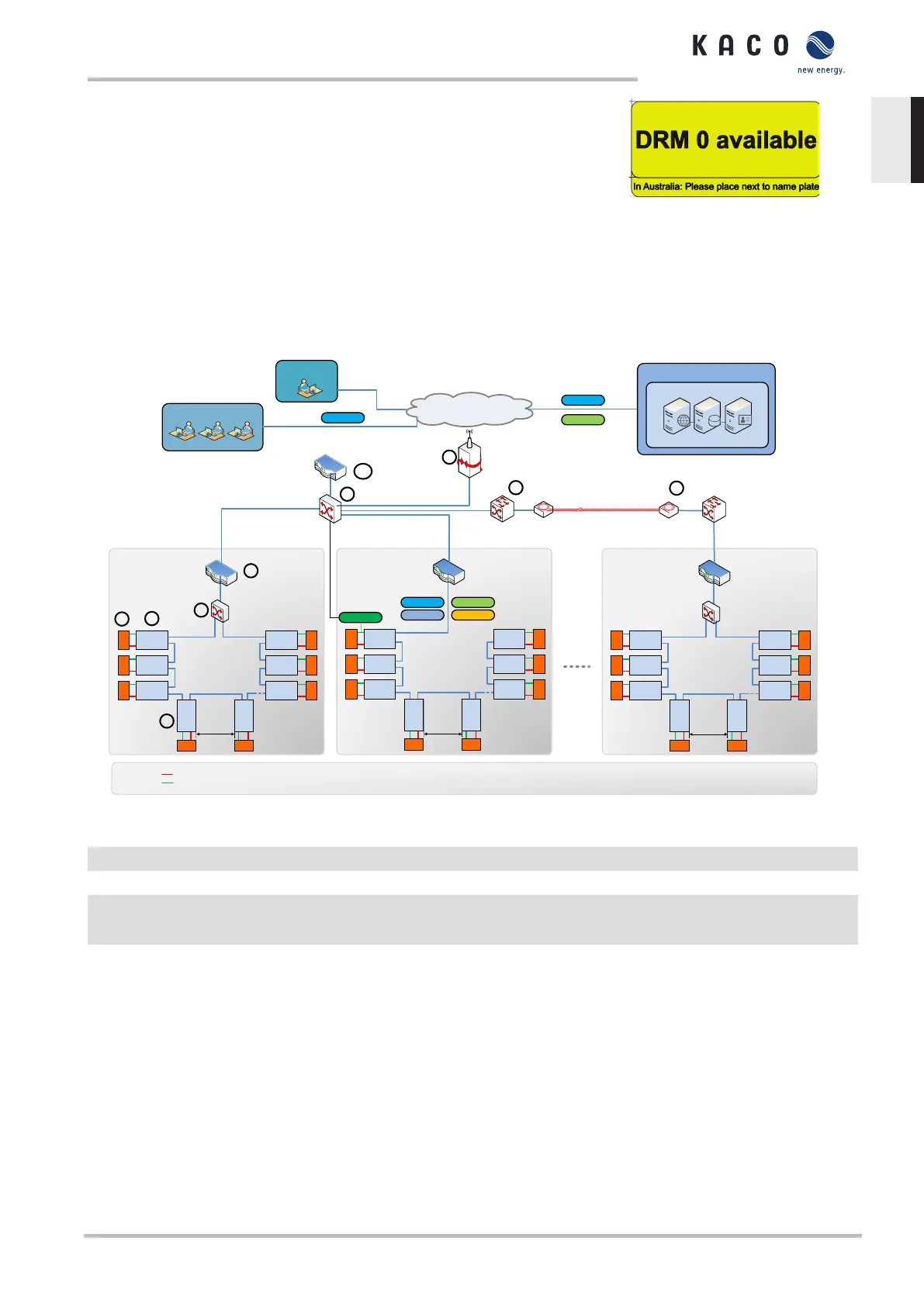
8.3 Network topologies
Segmentation of the system
SEGMENT 2
BP1
BP2
BP3
BPk
BPj
Ethernet
Line
Topology
max. 100m
SC
SC
SC
SC SC
SC
SC
SC
Segment
Controller
2)
SEGMENT 1
BP1
BP2
BP3 BPj
BPm
BPk
Ethernet
Ring
Topology
max. 100m
SC
SC
SC
SC SC
SC
SC
SC
Segment
Controller
2)
BP4
BP5
SEGMENT M
BP1
BP2
BP3 BPi
BPk
BPj
Ethernet
Ring
Topology
max. 100m
SC
SC
SC
SC SC
SC
SC
SC
Segment
Controller
2)
Max. 100m
Network
Segment Switch
(RSTP)
Main network switch
FO Switch
FO Switch
Fiber
Splicebox
Splicebox
Internet
Network
Segment Switch
(RSTP)
Gateway
VPN 3G/4G Router
BP4
BP5
BPi
BP4
BP5
max. 100 nodes/segment
typ. 10MW/segment
Legend:
SC: ARGUS
String Combiner
BP: blueplanet 125
Inverter
1): meteocontrol blue’Log XC
2): meteocontrol blue’Log XM
RS485
DC
RSTP: Rapid Spanning Tree
Protocol
MQTT
MODBUS/TCPFTP
HTTP(S)
MODBUS/RTU
MQTT: Messge Queuing
Telemetry Transport
Plant
Controller
1)
HTTP(S)
Cloud
meteocontrol Portal
WEB-
Server
Database-
Server
App-
Server
XMPP
Service
User
HTTP(S)
Fig.43: Segmentation of a plant
1 Gateway VPN 3G/4G router 6 Network segment switch
2 Main network switch 7 Inverter device
3 FO - switch (fibre optic) 8 String combiner
4 Slicebox (for fibre optic data transfer) 9 Connection cable and protocol
- DC / Modbus RTU / RS485
5 Segment Controller 10 Plant Controller
This illustration shows a possible variant for multiple segments. Depending on the local conditions, a different
positioning of the components may also be preferable (e.g. position Segment Controller at a central location
and connect in the segment switch via glass fibre cable).
Located directly after the Gateway VPN-Router, is the main network switch via which the segment con-
troller is connected in. With the corresponding system size (distance from main network switch to the
segment controller >100 m), it may also be necessary to connect in segments that are further away via a
glass fibre connection.
Within a segment, the KACO devices can be coupled to one another via the integrated switch in an Ethernet
daisy chain, whereby the segment controller is connected to the first element of the chain. This topology is dis-
played in segment 2, for example. A Segment Controller can manage up to 100 nodes. A node in this
sense is any data source that is monitored by the Segment Controller. (Example: 45 pairs consisting of in-
verter and string combiner (90 nodes) + 10 reserve nodes for other substation/segment data sources)
Manual Start-up | 8
KACO blueplanet 87.0 TL3 KACO blueplanet 92.0 TL3 KACO blueplanet 105 TL3 KACO blueplanet 110 TL3
KACO blueplanet 125 TL3 KACO blueplanet 137 TL3 KACO blueplanet 150 TL3 KACO blueplanet 155 TL3 KACO
blueplanet 165 TL3
Page 39
EN-US
 Loading...