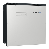
7.9.6 Connecting "Inverter Off"
Connect the Powador-protect (only in the case of 380/400V
blueplanet 87.0TL3 / 92.0TL3)
↻ The cable to the external grid protection device is available on the device.
↻ Cover of the device has been opened.
1. Loosen the cable fittings [ W_19]
2. Thread the connection cables through the cable fittings.
3. Connect wire A (+) to the terminal marked "INV OFF+" on the first device
via the "DO1" terminal of the protective device.
4. Connect wire B (-) to the terminal marked "INV OFF-" on the first device
via the "GND" terminal of the protective device.
5. Connect the other devices to one another as follows:
- Wire A (+) to wire A (+) and wire B (-) to wire B (-).
6. Tighten cable fitting [ W_19 / 22 In-Ibs ]
7. After commissioning: Configure the external Overvoltage protection
Powador-protect in the menu entry Properties / Functions Proper-
ties / functions.
RS485
B
A
GND
B
A
GND
-
D01
GND
4
3
2
1
RS485
B
A
GND
B
A
GND
-
+
INV
OFF
INV
OFF
+
1
2
x
x
y
y
INV Signal
Fig.38: Connect the device to
Powador-protect
Connect the external device
↻ The cable to the external grid protection device is available on the device.
↻ Cover of the device has been opened.
1. Loosen the cable fittings [ W_20]
2. Thread the connection cables through the cable fittings.
3. Connect wire A (+) from "COM" (11) on the terminal of the protective de-
vice to the terminal marked "INV OFF+" on the first device.
4. Connect wire B (+) from "NC" (12) on the terminal of the protective device
to the terminal marked "INV OFF-" on the first device.
5. Connect the other devices to one another as follows:
- Wire A (+) to wire A (+) and wire B (-) to wire B (-).
6. Tighten cable fitting [ W_20 / 13,27 In-Ibs ].
7. After commissioning: Configure the external Overvoltage protection
external device in the menu entry Properties / Functions Properties / func-
tions.
RS485
B
A
GND
B
A
GND
-
14 NO
24
21
RS485
B
A
GND
B
A
GND
-
+
INV
OFF
INV
OFF
+
1
2
min./ max.
10-24V(+/-20%)
/15mA-1A
x
x
y
y
12 NC
11 COM
22
INV OFF
INV ON
Fig.39: Connecting the device to
the external grid protection device
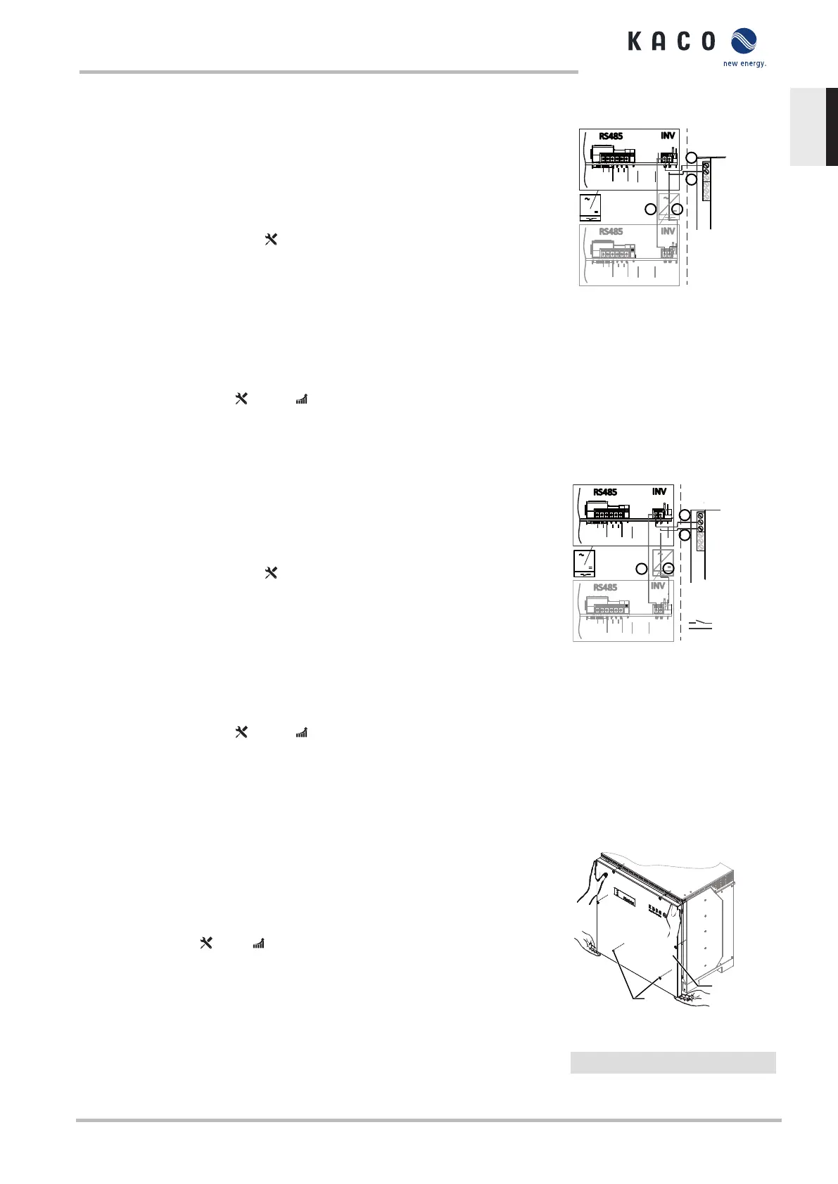
7.10 Sealing the connection area
↻ The grid connection has been prepared.
1. Lift the housing cover onto the housing and loosely tighten the fastening
screws.
2. Secure the housing cover by tightening all 6 screws in a diagonally oppo-
site sequence [ T_25/ 42.48 In-Ibs ].
ð The device has been mounted and installed.
ð Put the device into operation.
Fig.40: Closing the housing cover
1 Housing cover
3 Screws
Manual Installation | 7
KACO blueplanet 87.0 TL3 KACO blueplanet 92.0 TL3 KACO blueplanet 105 TL3 KACO blueplanet 110 TL3
KACO blueplanet 125 TL3 KACO blueplanet 137 TL3 KACO blueplanet 150 TL3 KACO blueplanet 155 TL3 KACO
blueplanet 165 TL3
Page 37
EN-US
 Loading...