Properties of the RS485 data line
Maximum number of connected bus devices 99 devices + 1 data monitor device or max. 49 devices and
49 string combiners + 1 data monitor device
Data cable Twisted, shielded.
Recommendation Black twisted pair for laying cable outside and in the
ground, 14 x 14 x 20 AWG
Gray twisted pair for dry and damp indoor spaces, 14 x 14 x
20 AWG
↻ To prevent interference during data transmission:
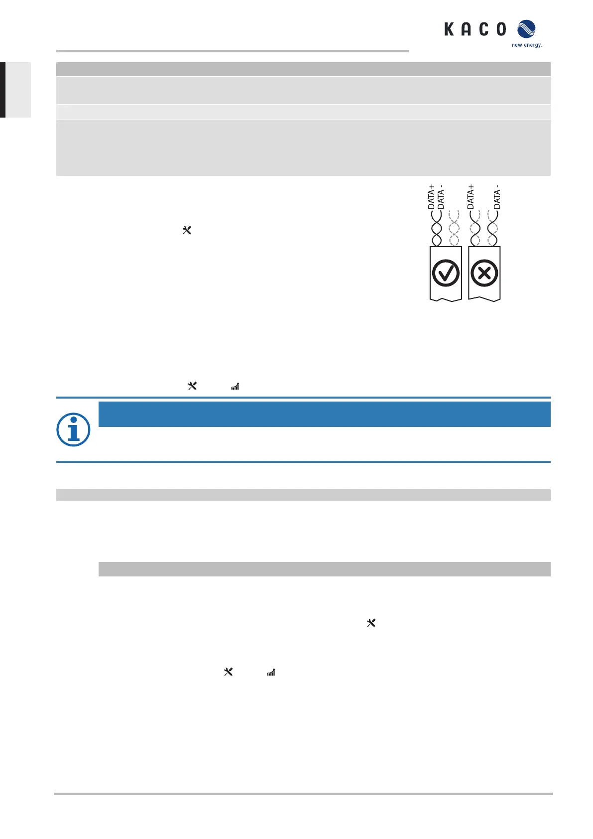
- Observe the wire pairing when connecting DATA+ and DATA-.
- Do not lay the RS485 bus line in the vicinity of live DC/AC cables.
1. Loosen the cable fitting [ W_20]
2. Thread the connection cables through the cable fitting.
3. To place the shield, strip the RS485 data cable at the position of the
shield clamp up to the wire mesh (approx. 20mm).
4. Clip the unsheathed RS485 data cable onto the shield clamp.
5. Connect the connection cable to the corresponding connection terminals.
6. The following must be connected to all inverters and to the data monitor
unit in the same way:
- Wire A (-) to wire A (-) and wire B (+) to wire B (+)
- GND to GND
7. Fixing the cable ties.
8. Tighten the cable fittings [ W_20 / 1.5 Nm]
Fig.37: Assignment of twisted-pair
wires
NOTE
When using the RS485 bus system, assign a unique address to every bus device (inverter, sensor)
and terminate the terminal units (see the “Settings” menu) .
↻ Check whether one of the devices represents the terminal unit.
F Only activate the terminating resistor on the communication circuit board of the terminal unit using the DIP switch.
ð RS485 connection made. Lay signal cable correctly.
7.9.5 Connecting external grid protection components
The contact is designed as an N/O contact and is labeled "ERR" or "Relay" on the circuit board.
Maximum contact load
DC 30 V/1A
↻ Connection area cover open.
1. Loosen the cable fitting to pass the signal cable through [ W_20]
2. Thread the connection cables through the cable fitting.
3. Attach the connection cables to the terminals.Overview [See section7.9.1}Page34]
4. Tighten the cable fitting [ W_20 / 1.5 Nm].
7 | Installation Manual
KACO blueplanet 87.0 TL3 KACO blueplanet 92.0 TL3 KACO blueplanet 105 TL3 KACO blueplanet 110 TL3
KACO blueplanet 125 TL3 KACO blueplanet 137 TL3 KACO blueplanet 150 TL3 KACO blueplanet 155 TL3
KACO blueplanet 165 TL3
Page 36
EN-US
 Loading...