Irrespective of the communication protocol used, the settling time “WMaxLim_Ena” is used in order to
transfer the new power value. Otherwise, the internally configured value will be used.
The additional ramp time “WMacLimPct_RmpTms” specifies the jump time from a power value to the
new power value.
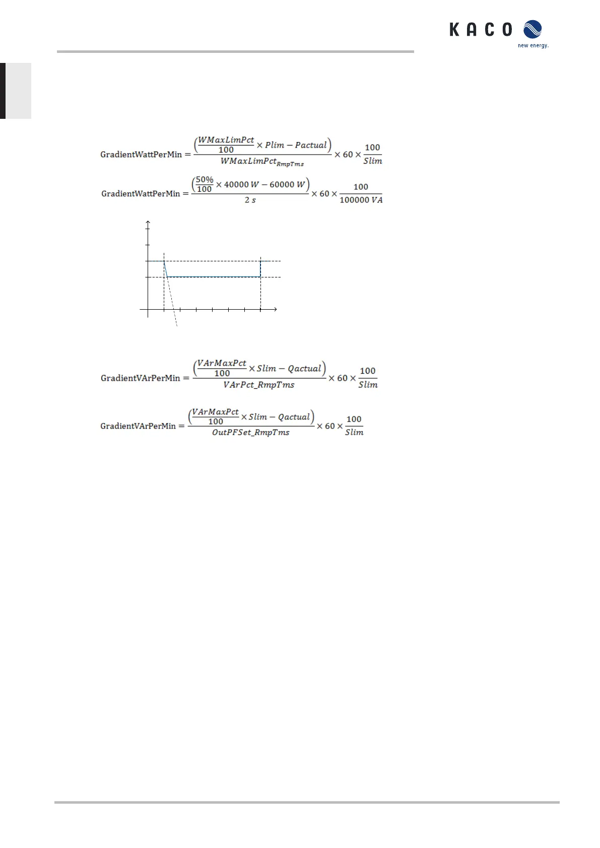
The following formulae are used to calculate the gradient S
lim/min
:
Power / kVA resp. kW
Time / s
S
lim
=100
P
lim
=80
P
fb
=60
WMaxLimPct =40
10 20 30 40 50 60 70
Gradient = -600 % S
lim
/min
Fig.73: Power gradient according to sample parameters and calculation
The following formulae are used to calculate the Q filter parameter and cos-phi gradient:
Fig.74: Formula for calculating the Q filter parameter
Fig.75: Formula for calculating the cos-phi gradient (internal power gradient)
10.2.2 Voltage-dependent power reduction P(U)
If it is not possible to compensate adequately for voltage increase in the upstream distribution network
by consumption of reactive power, it may be necessary to curtail the active power. In this case, P(U)
control is available for making optimum use of the capacity of the upstream grid.
P(U) control reduces the active power that is fed-in as a function of the grid voltage using a prescribed
characteristic curve as a basis. The P(U) control is implemented as an absolute power limit. The actual
power of the inverter may vary freely below this limit based on possible fluctuation of the available
power or set point, but will never increase above the absolute power limit.
[See figure 76: Example characteristic without hysteresis [}Page83] and [See figure 77: Example
characteristic with hysteresis and a deactivation threshold lower than the activation threshold.
[}Page83] are two example configurations. In case of the Figure 1 without hysteresis the function is
activated once the voltage exceeds the configured voltage of data point 1 (dp1). The power limit fol-
lows the characteristic, a straight line between dp1 and dp2. The function is deactivated once the volt-
age falls below dp1. In case of [See figure 77: Example characteristic with hysteresis and a deactiva-
tion threshold lower than the activation threshold. [}Page83] the function is activated once the volt-
age exceeds the configured voltage of dp2. dp1 is not activating the function in this case as the power
limit remains at 100%. The power limit follows the characteristic, a straight line between dp2 and dp3,
but due to the activated hysteresis, the power limit is not increased at falling voltage. The function is
deactivated once the voltage falls below dp1.
10 | Specifications Manual
KACO blueplanet 87.0 TL3 KACO blueplanet 92.0 TL3 KACO blueplanet 105 TL3 KACO blueplanet 110 TL3
KACO blueplanet 125 TL3 KACO blueplanet 137 TL3 KACO blueplanet 150 TL3 KACO blueplanet 155 TL3
KACO blueplanet 165 TL3
Page 82
EN-US
 Loading...