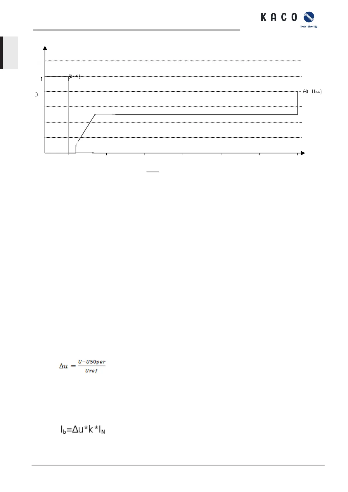
(1 ; 0)
(1 ; 0,1)
(3 ; 0,5)
Fig.84: Immunity to interference characteristic curve relative to the nominal voltage (p.u.) of the blueplanet 125.0TL3
The inverters can ride through voltage swells provided the voltage level does not remain above the continuous
operation voltage range for longer than 100 s and does not increase beyond the short-term max. operating volt-
age range (up to 100s). The values specific to each inverter can be found here.
The interface protection (voltage,frequencey, ant-islanding) integrated in the inverter is configurable in a range
allowing the behaviour above. However, if the interface protection setting is limiting the voltage time characteris-
tic, the interface protection will trip and interrupt the ride through as configured.
10.3.2 Dynamic grid support using a fast feeding of residual current
When dynamic grid support using a fast feeding of residual current is activated, then residual current
is fed in in addition to the immunity to interference properties against drops and spikes described
above.
The inverter adapts its current feed as soon as a drop or spike incident occurs in order to bolster the
grid voltage. The support takes place in the event of voltage drop in the form of over-excited reactive
current (corresponds to a capacitive load), in the event of voltage spike in the form of over-excited re-
active current (corresponds to an inductive load). In the reactive current priority mode, the effective
current is reduced to the extent necessary to comply with the limits of the maximum continuous current
of the inverter.
A dip or swell is detected if either the normal operating voltage range setting is exceeded by at least
one phase-phase or phase-neutral voltage, or if a step in the positive or negative sequence compo-
nent of the voltage greater than the deadband setting occurs. The magnitude of the voltage step of the
positive and negative sequence voltage equates to the difference between the pre-fault voltage and
the actual voltage based on the reference voltage. The pre-fault voltage is calculated as a 50-periods
mean value.
Fig.85: Formula n° 1
The reactive current is adapted using a response time of <20 ms and a transient time of <60 ms after
the incident has occurred. Responses to changes in the voltage during the incident or to the voltage
recovery at the end of the incident take place with the same dynamic.
The formula for calculating the dynamic reactive current that is fed for the positive or negative phase
sequence voltage is:
Fig.86: Formula n° 2, depending from the nominal current IN of the inverter
10 | Specifications Manual
KACO blueplanet 87.0 TL3 KACO blueplanet 92.0 TL3 KACO blueplanet 105 TL3 KACO blueplanet 110 TL3
KACO blueplanet 125 TL3 KACO blueplanet 137 TL3 KACO blueplanet 150 TL3 KACO blueplanet 155 TL3
KACO blueplanet 165 TL3
Page 88
EN-US
 Loading...