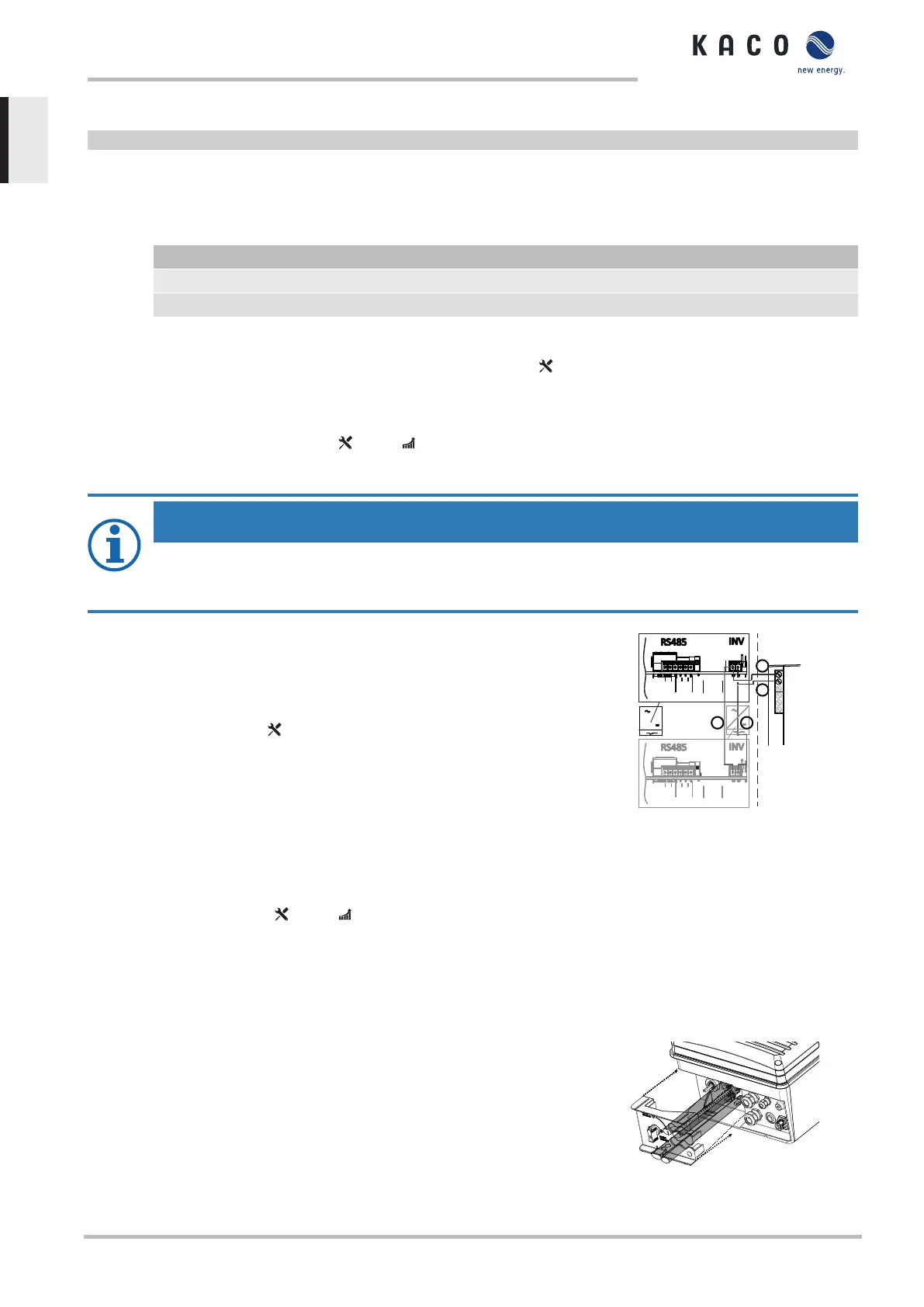
↻ Check whether one of the devices represents the terminal unit.
F Only activate the terminating resistor on the communication circuit board of the terminal unit using the DIP switch.
ð RS485 connection made. Lay signal cable correctly.
7.6.5 Connecting external grid protection components
The contact is designed as an N/O contact and is labelled "ERR" or "Relay" on the circuit board. []
Maximum contact load
DC 30 V / 1 A
AC 250 V / 1 A
↻ Connection area cover open.
1. Loosen the cable fitting to pass the signal cable through [ W_20]
2. Thread the connection cables through the cable fitting.
3. Attach the connection cables to the terminals. [See section7.6.1}Page27]
4. Tighten the cable fitting [ W_20 / 1,5 Nm]
7.6.6 Inverter Off connection
NOTE
The digital input of the device is intended for connection of a Powador-protect. When using devices from other
manufacturers or in combination with KACO inverters, interface switches as a minimum must be used for shut-
ting down devices from other manufacturers.
Connect Powador-protect
↻ The cable to the external grid protection device is available on the device.
↻ Cover of the device has been opened.
1. Undo the cable fittings [ W_20]
2. Pass the connection cable through the cable fittings.
3. Connect wire A (+) to the terminal marked "INV OFF+" on the first device via the
"DO1" terminal of the protective device.
4. Connect wire B (-) to the terminal marked "INV OFF-" on the first device via the
"GND" terminal of the protective device.
5. Connect the other devices to one another as follows:
- wire A (+) to wire A (+) and wire B (-) to wire B (-).
6. Tighten the cable fitting [ W_20 / 1.5 Nm]
7. After commissioning: Configure the external Overvoltage protection
Powador-protect in the menu entry Properties / Functions Features /
Functions.
RS485
B
A
GND
B
A
GND
-
D01
GND
4
3
2
1
RS485
B
A
GND
B
A
GND
-
+
INV
OFF
INV
OFF
+
1
2
x
x
y
y
INV Signal
Fig.37: Connecting the device to
Powador-protect
7.7 Sealing the connection area
↻ Grid connection is prepared.
1. Feed the cables into the cover.
2. Place the cover at the marked position and click into place.
3. Set the DC isolator switch to “1”.
ð Put the device into operation.
Fig.38: Close the connection cover
7 | Installation Manual
KACO blueplanet 3.0 TL3 KACO blueplanet 4.0 TL3 KACO blueplanet 5.0 TL3 KACO blueplanet 6.5 TL3 KACO
blueplanet 7.5 TL3 KACO blueplanet 8.6 TL3 KACO blueplanet 9.0 TL3 KACO blueplanet 10.0 TL3
Page 30
EN
 Loading...