- 7
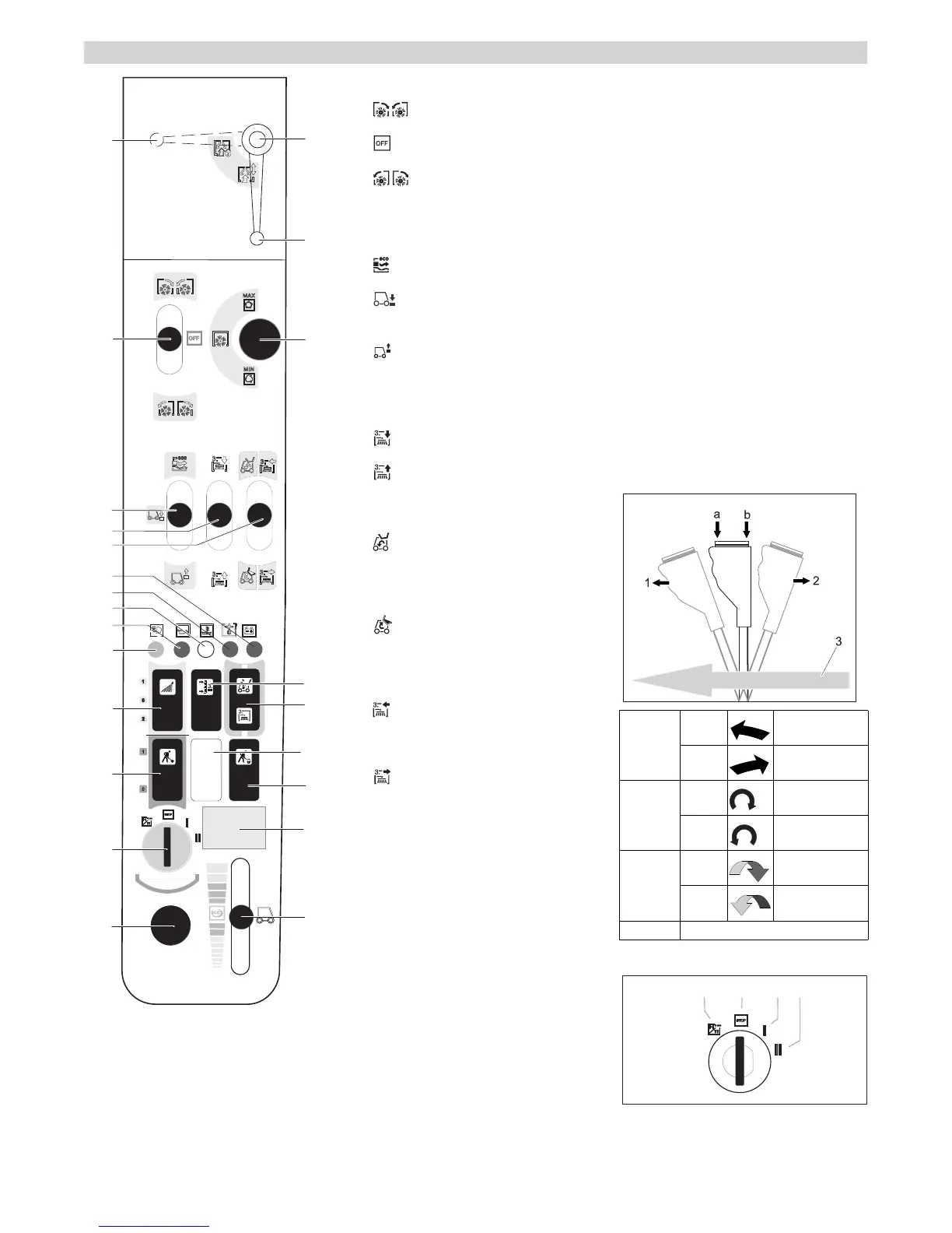
A Control lever 2.PTO connection
Side brush on, sweep
Side brush stop
Side brush on, reversal of rota-
tion
B Control lever front power lift
Lower work appliance, floating
Lower work appliance and press
down
Lift work appliance (only while en-
gine is running)
C Control lever AUX 1 connection
3. Lower the side brush (option)
3. Lift the side brush (option)
D Control lever AUX 2 connection
Change-over switch (14) in waste
container position: Retracting waste
container (only while the motor is run-
ning)
Change-over switch (14) in waste
container position: Emptying waste
container, (only while the motor is run-
ning)
Change-over switch (14) in 3rd side
brush position (option): Swivel in the
side brush
Change-over switch (14) in 3rd side
brush position (option): Swivel out the
side brush
Note: In connection with the front appliance
carrier and the weed broom a multifunction
lever is available instead of the control le-
ver (optional)
E For working with the suction port
(optional)
Position E1 - suction port not locked
Position E2 - suction port locked
1 Warning lamp for battery charging con-
trol
2 Warning lamp hydraulic oil pressure
3 Warning light coolant temperature
4 Warning lamp oil pressure
5 Indicator lamp for high beams
6 Switch
1 Irrigation of side brush on
0 Irrigation of side brush off
2 Switch on water circulation system
(option)
7 Buttons
Position 1: Work hydraulics Main PTO
on
Position 0: Work hydraulics Main PTO
off
8 Ignition lock
9 On board socket 12 V
10 Setting the motor rpm
11 Operating hours meter for motor
12 Pushbutton with locking mechanism
Work hydraulics Main PTO constantly
on
Function only in connection with locked
parking brake and button 7
13 Not assigned
14 Change-over switch
Waste container / 3rd side brush (op-
tion)
15 Pushbutton, controls socket E1
Tilt the side brush (option)
16 Setting speed PTO
Setting the speed of the side-brushes
A Filament symbol : Pre-heat
B Position STOP: Motor off
C Position 1: Ignition on
D Position 2: Start the engine
Console MC 50
A
B
D
E
C
E2
E1
1
2
3
4
5
6
7
8
9
10
11
12
13
14
15
16
Function of the multi-function lever (joy-
stick)
0 1 swivel to the
left
2 swivel to the
right
a 1 incline clock-
wise
2 incline anti-
clockwise
b 1 tipping to the
front
2 tipping toward
the rear
3 Forward travel direction
Ignition lock
A
B
C
D
9EN
 Loading...