Project Planning
1610
Name: Basis
KEB COMBIVERT F5
04.05.04
Chapter Section Page Date
© KEB Antriebstechnik, 2002
All Rights reserved
10.1.3 Cable and Fuses
By means of this section you can check whether you can still optimize your machine
with regard to the material usage. The specifications are derived from the DIN VDE
0298 Part 4. The values apply approximately and only for the intended operation. In
border cases always proceed in accordance with the above standard. The following
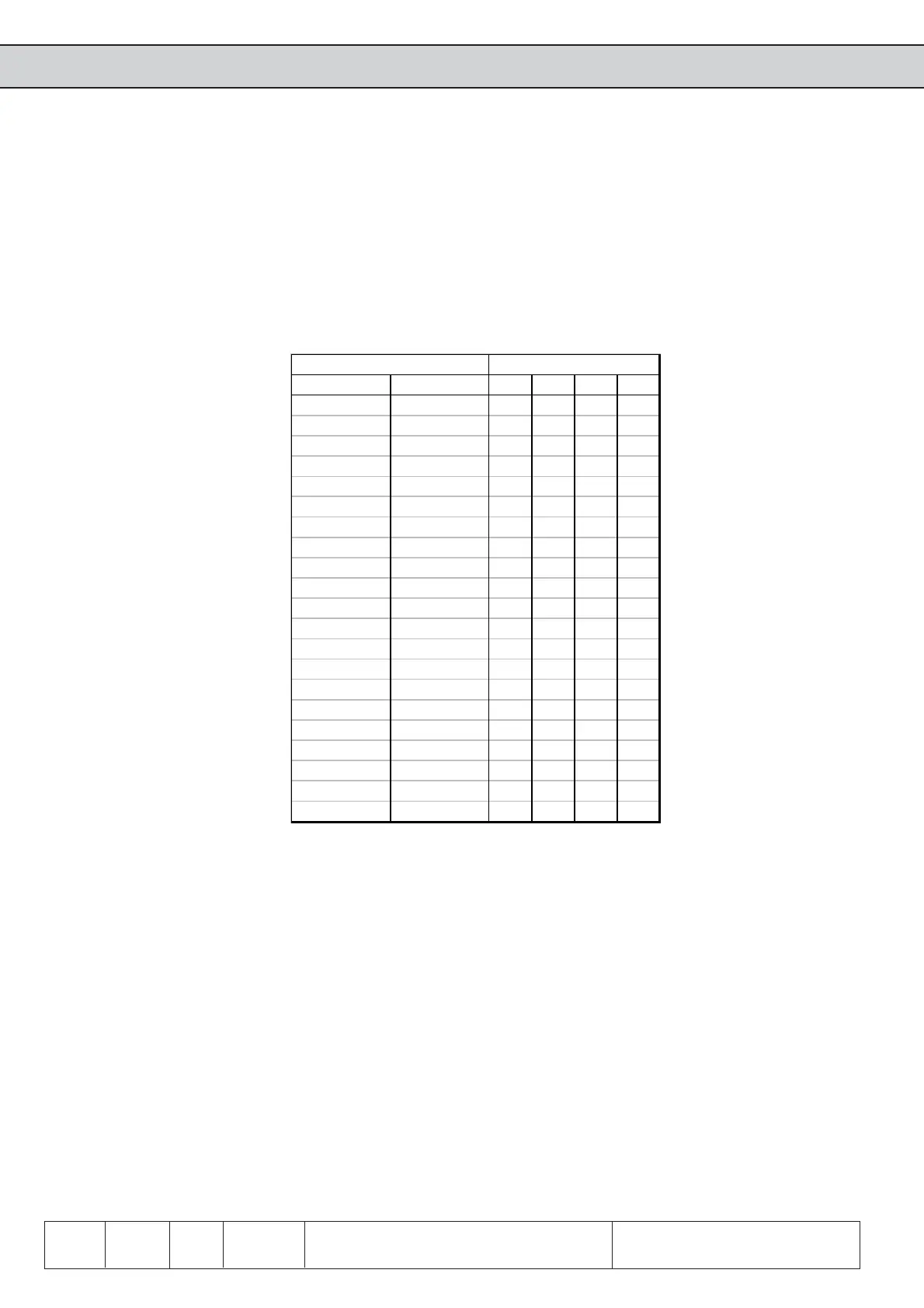
table shows the current-carrying capacity of 3- and/or 5-wire PVC cables (i.e. 2 and/or
3 loaded wires) in dependence on the ambient temperature. The current is to be laid
out to the input current of the frequency inverter.
Standard Alternatively 30°C 40°C 45°C 50°C
0,5 mm² - 7 6 6 5
0,75 mm² - 12 10 10 9
1 mm² - 15131311
1,5 mm² - 18 16 15 13
2,5 mm² - 26 23 22 18
4 mm² 2 x 1,5 mm² 34 30 29 24
6 mm² 2 x 2,5 mm² 44 38 37 31
10 mm² 2 x 4 mm² 61 53 51 43
16 mm² 2 x 6 mm² 82 71 69 58
25 mm² 2 x 10 mm² 108 94 91 77
35 mm² 2 x 16 mm² 135 117 113 96
50 mm² 2 x 16 mm² 168 146 141 119
70 mm² 2 x 25 mm² 207 180 174 147
95 mm² 2 x 35 mm² 250 218 210 178
120 mm² 2 x 50 mm² 292 254 245 207
150 mm² 2 x 50 mm² 330 287 277 234
185 mm² 2 x 70 mm² 394 343 331 280
240 mm² 2 x 95 mm² 450 392 378 320
300 mm² 2 x 95 mm² 507 441 426 360
400 mm² 2 x 150 mm² 661 575 555 469
500 mm² 2 x 185 mm² 774 673 650 550
Current in [A] atCross section of feed cable
The use of special cables or the way of laying the cables allows even higher currents
(see DIN VDE 0298 Part 4). The motor cable must correspond to the cross-section of
the mains cable.
If in the case of long lines (>30m) still maximum torque is required at the motor shaft,
the cable should be dimensioned for the next larger cross-section in order to reduce
line resistances.
Mains fuses are to be designed for the rated input current of the inverter. The current/
time-characteristic of the fuse must be slow-acting in order to avoid premature tripping
when utilizing the power reserves of the inverter.
 Loading...


