High Voltage SourceMeter Instrument User's Manual Section 6: Measure I-
V characteristics of FETs
2470-900-01 Rev. A / May 2019 6-3
Set up external hardware triggers
To enable synchronization between the two 2470 instruments for stepping and sweeping voltages,
connect the external triggers of each instrument to the other. The cabling you use depends on which
2470 programming command set you choose to control the test.
Connections for the SCPI command set
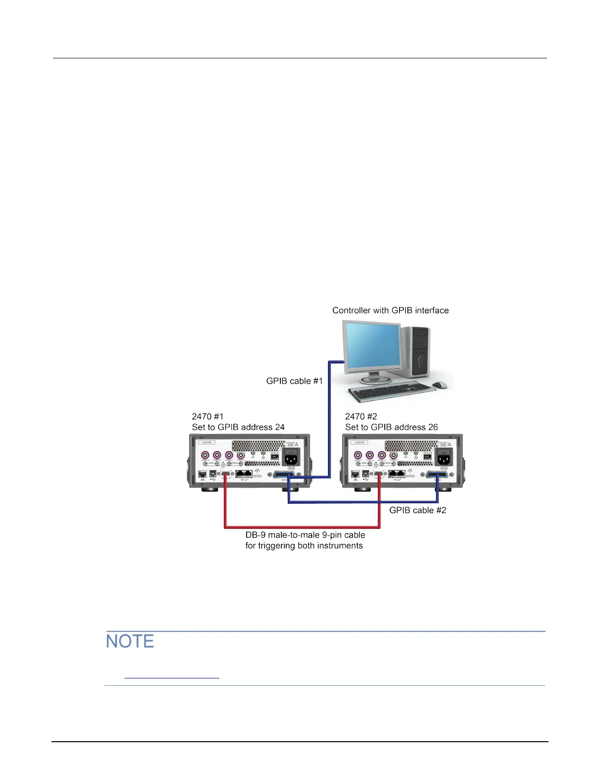
If you are using the SCPI command set, connect a DB-9 male-to-male cable between the digital I/O
connectors on the back of each of the instruments, as shown in the figure below.
For more detailed information about the digital I/O connector pins, see "Digital I/O" in the 2470
Reference Manual.
Figure 29: GPIB and DB-9 connections for the SCPI programming example
The figure above also shows the communication cable connections if you are using the GPIB remote
communication interface. GPIB cable #1 connects the GPIB port on the computer (controller) to the
IEEE-488 connector on the rear panel of 2470 #1. GPIB cable #2 connects the IEEE-488 connectors
of the two 2470s.
Each 2470 must have a different GPIB address. You can set this up using the front panel. For details,
see Set the GPIB address (on page 3-4
).

 Loading...


