APPLICATIONS
5.4.4 Model 642 .Electrometer Calibration
Using the Model 263 as described above eliminates the
need for the following equipment:
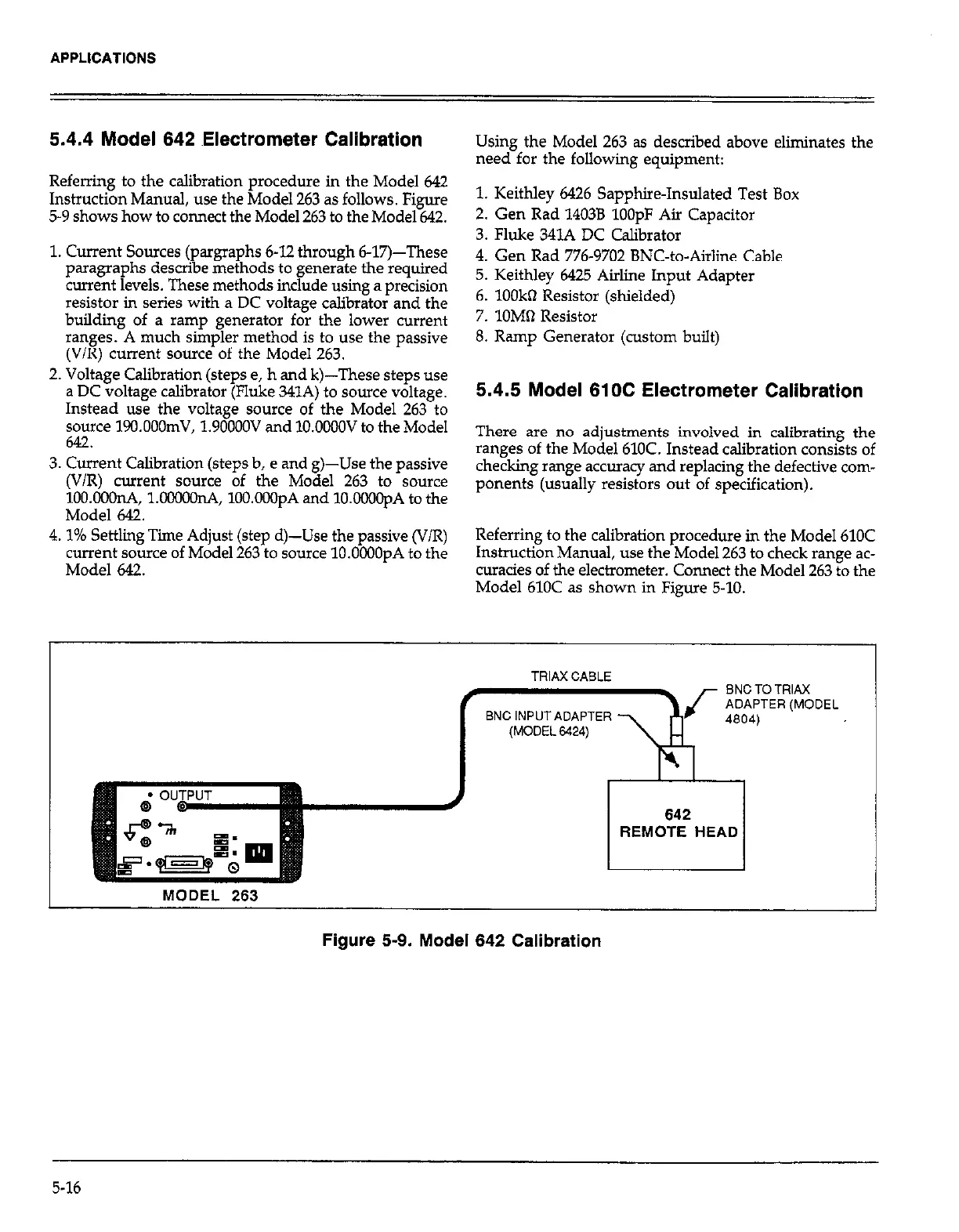
Referring to the calibration procedure in i
the Model 642
Instruction Manual, use the Model 263 as f 0110~s. Figure
1. Keithley 6426 Sapphire-Insulated Test Box
5-9 shows how to connect the Model 263 to
the Model 642.
2. Gen Rad 14038
1OOpF Air Capacitor
1. Current Sources (pargraphs 6-12 through 6-17)-These
paragraphs describe methods to generate the required
current levels. These methods include using a precision
resistor in series with a DC voltage calibrator and the
building of a ramp generator for the lower current
ranges. A much simpler method is to use the passive
(V/R) current source of the Model 263.
2. Voltage Calibration (steps e, h and k)-These steps use
a DC voltage calibrator (Fluke 341A) to source voltage.
Instead use the voltage source of the Model 263 to
source 19o.OOOmV, 1.9OOOOV and lO.OOMW to the Model
642.
3. Current Calibration (steps b, e and g)-Use the passive
(V/R) current source of the Model 263 to source
lOO.OOOnA, 1.00000nA, 100.OO3pA and lO.OOOOpA to the
Model 642.
4.1% Settling Time Adjust (step d)-Use the passive (V/R)
current source of Model 263 to source lO.OCOOpA to the
Model 642.
3. Fluke 341A DC Calibrator
4. Gen Rad 776-9702 BNC-to-Airline Cable
5. Keithley 6425 Airline Input Adapter
6. 1OOkQ Resistor (shielded)
7. lOM61 Resistor
8. Ramp Generator (custom built)
5.4.5 Model 610C Electrometer Calibration
There are no adjustments involved in calibrating the
ranges of the Model 610C. Instead calibration consists of
checking range accuracy and replacing the defective com-
ponents (usually resistors out of specification).
Referring to the calibration procedure in the Model 610C
Instruction Manual, use the Model 263 to check range ac-
curacies of the electrometer. Connect the Model 263 to the
Model 610C as shown in Figure 5-10.
REMOTE HEAD
MODEL 263
Figure 5-9. Model 642 Calibration
5-16
 Loading...
