With either error, the instrument will be completely in-
operative. In the event of a ROM error try replacing U47 and
for a RAM error, try replacing U46.
If a calibration error occurs, the two exponent decimal
points will flash. The instrument will be functional under
these conditions, but calibration is not accurate. Use the
calibration procedures in paragraph 8-4 of this section to
calibrate the instrument. If an NVRAM error persists after
calibration, then the NVRAM may be defective. Try
replacing U15 and U41.
8.7.3 Display Test and Software Revision
This test displays all digit segments allowing the user to
check for defects and displays the current revision level of
the software installed in the unit. Perform the following
steps as follows:
1. Turn on the instrument while holding in the COUL but-
ton. The normal power up tests on RAM, ROM, and
NVRAM will be performed (see paragraph 8.8.1) and
then all display segments and indicators will turn on
and remain on as long as the COUL button is held in.
2. Release the COUL button. The software revision level
will be displayed briefly. For example, if the sofhvare
revision level is Al, then the following message will be
displayed briefly:
Al
The instrument will now display a value terminated
with a “T”. This number represents temperature infor-
mation and should be between 25,000 and 45,000. A
value outside of this range indicates a problem with the
temperature compensation circuitry.
3. To return to normal operation, turn the instrument off
and then on again.
8.7.4 Power Supply Checks
All power supply voltages should be checked first to make
sure they are within the required limits. If the various
operating voltages are not within the required limits,
troubleshooting the remaining circuitry can be quite
difficult.
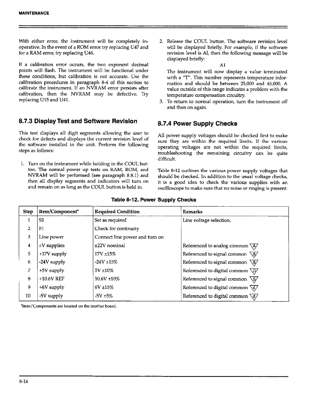
Table 8-12 outlines the various power supply voltages that
should be checked. In addition to the usual voltage checks,
it is a good idea to check the various supplies with an
oscilloscope to make sure that no noise or ringing is present.
Table 8-12. Power Supply Checks
step Item/Component* Required Condition
Remarks
1
52 Set as required Line voltage selection.
2 Fl
Check for continuity
3
Line power
Connect line power and turn on
4 *V supplies f22V nominal Referenced to analog common v
5 +17V supply 17v i15% Referenced to signal common v
6
-24v supply -24V +15% Referenced to signal common v
7
+5v supply 5v *lo% Referenced to digital common v
8
+10.6V REF
10.6V +lO% Referenced to signal common v
9
+6V supply 6V *15% Referenced to digital common v
10 -5v supply -5v *5% Referenced to digital c~mtn~n v
8-16
 Loading...
