IEEE-488 PROGRAMMING
that additional instruments are used. Depending on pro-
gramming, all data
may
be routed through the controller,
or it may be sent directly from one instrument to another.
ne&d to the controller. Some controllers have an
IEEE-488 type connector, while others do not. Consult
the instruction manual for your controller for the pro-
per connecting method.
4.2.2 Cable Connections
NOTE
The IEEE-488 bus is limited to a maximum of 15
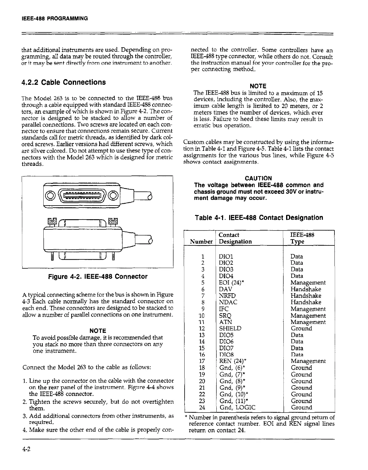
The Model 263 is to be connected to the IEEE-488 bus
through a cable equipped with standard IEEE-488 connec-
devices, including the controller. Also, the max-
tars, an example of which is shown in Figure 4-2. The con-
imum cable length is limited to 20 meters, or 2
nectar is designed to be stacked to allow a number of
meters times the number of devices, which ever
parallel connections. Two screws are located on each con-
is less. Failure to heed these limits may result in
nectar
to ensure that connections remain secure. Current
erratic bus operation.
standards call for metric threads, as identified by dark col-
ored screws. Earlier versions had different screws, which
Custom cables may be constructed by using the informa-
are silver colored. Do not attempt to use these type of con-
tion in Table 4-l and Figure 4-5. Table 4-1 lists the contact
nectars with the Model 263 which is designed for metric
assignments for the various bus lines, whiie Figure 4-5
shows contact assignments.
Figure 4-2. IEEE-488 Connector
A typical connecting scheme for the bus is shown in Figure
4-3 Each cable normally has the standard connector on
each end. These connectors are designed to be stacked to
allow a number of parallel connections on one instrument.
NOTE
To avoid possible damage, it is recommended that
you stack no more than three connectors on any
one instrument.
Connect the Model 263 to the cable as follows:
1. Line up the connector on the cable with the connector
on the rear panel of the instrument. Figure 4-4 shows
the IEEE-488 connector.
2. Tighten the screws securely, but do not overtighten
them.
3. Add additional connectors from other instruments, as
required.
4. Make sure the other end of the cable is properly con-
r-
Number
1
2
3
4
5
6
7
t
10
11
12
13
:t
16
is’
19
20
21
22
23
CAUTION
The voltage between IEEE-488 common and
chassis ground must not exceed 30V or instru-
ment damage may occur.
Table 4-l. IEEE-488 Contact Designation
contact
IEEE-488
Designation
Type
24
._
DIOl
Data
D102
Data
D103
Data
D104
Data
EOI (24)*
Management
DAV
Handshake
NRFD
Handshake
NDAC
Handshake
IFC
Management
SRO
AT%
Management
Management
SHIELD
Ground
DI05
Data
D106
Data
D107
Data
DI08
Data
REN (24)*
Management
Gnd, (6)*
Ground
Gnd, (7)*
Ground
Gnd, (8)*
Ground
Gnd. (9)*
Gnd; (lb)*
Ground
Ground
Gnd, (ll)*
Ground
Gnd, LOGIC
Ground
. .
.~
Number
in parenthesis reters to signal ground return ot
reference contact number. EOI and REN signal lines
return on contact 24.
4-2
 Loading...
