OPERATION
3.2.2 Line Power Connections
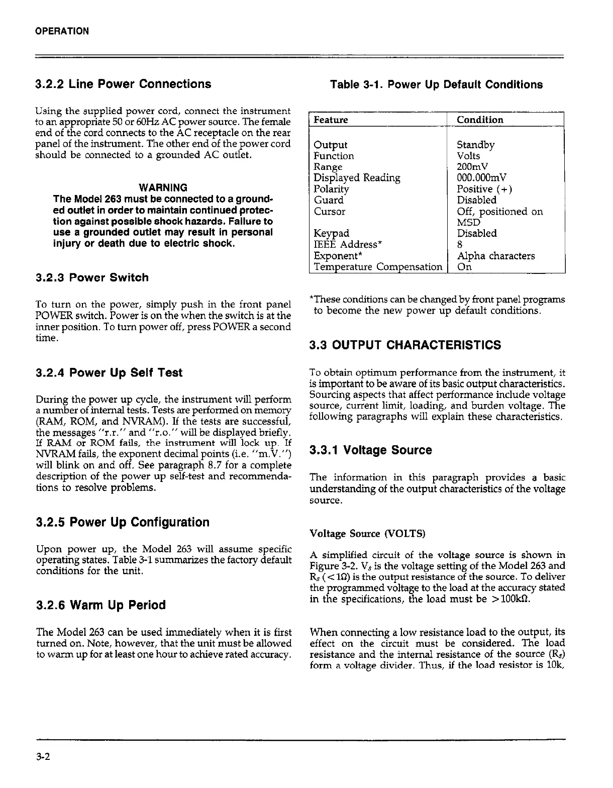
Table 3-1. Power Up Default Conditions
Using the supplied power cord, connect the instrument
to an appropriate 50 or 6OHz AC power source. The female
end of the cord connects to the AC receptacle on the rear
panel of the instrument. The other end of the power cord
should be connected to a grounded AC outlet.
Feature Condition
WARNING
The Model 263 must be connected to a ground-
ed outlet in order to maintain continued protec-
tion against possible shock hazards. Failure to
use a grounded outlet may result in personal
injury or death due to electric shock.
output
Standby
Function Volts
Range 2OOmV
Displayed Reading OOO.OOOmV
Polarity Positive (+ )
Guard Disabled
Cursor
Off, positioned on
MSD
Keypad Disabled
IEEE Address*
8
Exponent* Alpha characters
Temperature Compensation On
3.2.3 Power Switch
To turn on the power, simply push in the front panel
POWER switch. Power is on the when the switch is at the
inner position. To turn power off, press POWER a second
time.
3.2.4 Power Up Self Test
During the power up cycle, the instrument will perform
a number of internal tests. Tests are performed on memory
(RAM, ROM, and NVRAM). If the tests are successful,
the messages “r.r.” and “r.0.” will be displayed briefly.
If RAM or ROM fails, the instrument will lock up. If
NVRAM fails, the exponent decimal points (i.e. “m.V.“)
will blink on and off. See paragraph 8.7 for a complete
description of the power up self-test and recommenda-
tions to resolve problems.
3.2.5 Power Up Configuration
Upon power up, the Model 263 will assume specific
operating states. Table 3-1 summarizes the factory default
conditions for the unit.
3.2.6 Warm Up Period
The Model 263 can be used immediately when it is first
turned on. Note, however, that the unit must be allowed
to warm up for at least one hour to achieve rated accuracy.
*These conditions can be changed by front panel programs
to become the new power up default conditions.
3.3 OUTPUT CHARACTERISTICS
To obtain optimum performance from the instrument, it
is important to be aware of its basic output characteristics.
Sourcing aspects that affect performance include voltage
source, cun‘ent limit, loading, and burden voltage. The
following paragraphs will explain these characteristics.
3.3.1 Voltage Source
The information in this paragraph provides a basic
understanding of the output characteristics of the voltage
source.
Voltage Source (VOLTS)
A simplified circuit of the voltage source is shown in
Figure 3-2. Vs is the voltage setting of the Model 263 and
Rs ( < ln) is the output resistance of the source. To deliver
the programmed voltage to the load at the accuracy stated
in the specifications, the load must be > 1OOkQ.
When connecting a low resistance load to the output, its
effect on the circuit must be considered. The load
resistance and the internal resistance of the source (R,)
form a voltage divider. Thus, if the load resistor is lOk,
3-2
 Loading...
