MAINTENANCE
8.75 Logic and Switching FET States
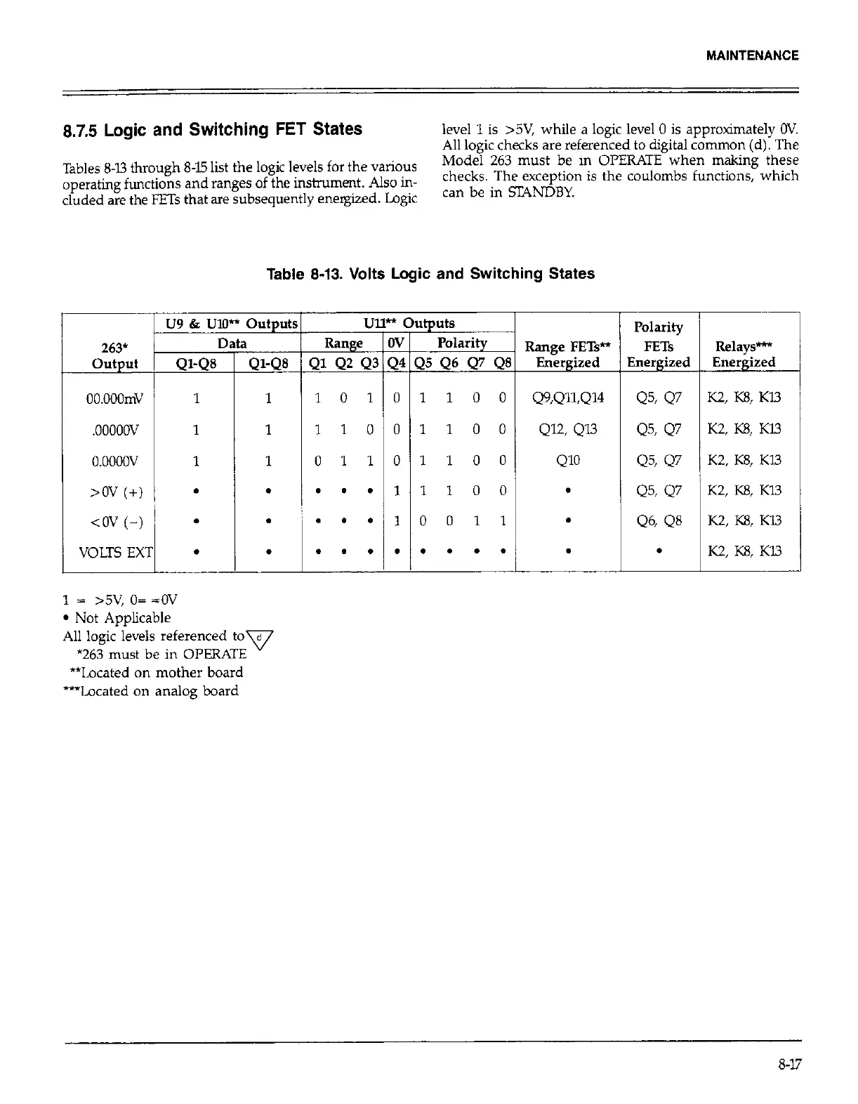
level 1 is >5V, while a logic level 0 is approximately OV.
All logic checks are referenced to digital common(d). The
Tables 8-13 through 845 list the logic levels for the various
Model 263 must be in OPERATE when making these
operating functions and ranges of the instrument. Also in-
checks. The exception is the coulombs functions, which
eluded are the FETs that are subsequently energized. Logic
can be in SRNDBY.
Table 8-13. Volts Logic and Switching States
u9 & IJIll** Outputr
oo.ooomv
1
.ooooov
1
o.oooov
1
>ov (+) l
<()v (-) ~ .
VOLTS EXT
l
1
Ql-Q8
1
1
1
.
.
.
1 = >5V, o= =ov
l
Not Applicable
All logic levels referenced tov
*263 must be in OPERATE
**Located on mother board
***Located on analog board
U:
Range
21 42 QS
1 0 1
1 1 0
0 1 1
. . .
. . .
. . .
* ou uts
IV Polarity
Range FETs*
Energized
Q9,Qll,Q14
QQ Qn
Ql’J
.
.
.
I
Polarity
FETs
3nergized
Q51 Q7
Q5, Q7
Q5, Q7
Q5, Q7
Q6, Q8
.
Relays-
Energized
K2, K23, Kl3
K2, KE, Kl3
K2, K8, Kl3
K2, K8, KU
K2, K8, K13
K2, KS, Kl.3
S-17
 Loading...
