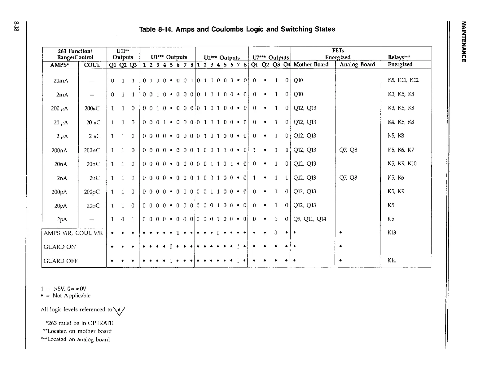
Table 8-14. Amps and Coulombs Logic and Switching States
263 Function/
Ull**
FETs
Range/Control Outputs
u1- outputs
u2- Outputs
u7- outputs
Energized
AMPS’
COUL QlQ2Q3 123456781234567BQlQ2Q3Q4MotherBoard
Analog Board
20mA 0 1 1
0100*001010000’0 0
l 1 0 QlO
2mA 0 11 0010’00001tl100’0 0
l
1 0 QlO
200 ,,A 200& 11
0 0010’000010100’0 0
l
1 0 Q12, Q13
20 ,,A 20 ,LC 11 0 0001 .000010100’0 0
- 1 0 Q12, Q13
2~4 2
WC 11 0 0000’000010100’0 0
l
1 0 Q12, Q13
200nA 200nC 11 0 0000’000100110.0 1
l
1 1 Q12, Q13
47, QS
~ 2OOpA 20nA ~OQA 2nA 2pA 2oopc 20nC 2opc 2nc
11
11 11 1 1 0 1 0 0
0
0 1
0000’000001101*0
0000*000100100*0 0000.000001100’0
0000’000000100’0
0000 .000000100’0 0
0
0
0
1
l l l l
- 1 1 1 1 1 0 0 0 0 1 Q12, Q12, Q12, Q9, Q12, Qll, Q13 Q13 Ql3 Q13
Q7, QS
Relays-
Energized
K8, Kll, K12
K3, K5, K8
K3, K5, K8
K4, K5, K8
K5, K8
K5, K6, K7
K9, K6 K9 KlO Q14 K5 K5, K5, K5, K5
iMPS V/R, COUL V/R
l l l . . . . . I..... 0 . . . . .
. 0 . . .
K13
GUARD ON . . . . . . . 0 . . . . . . . . . 1..
. . . . .
GUARD OFF . . . . . . . I......... 1..
. . . . . K14
1 = >5v, o= =ov
l
= Not Applicable
All logic levels referenced to d
v
‘263 must be in OPERATE
“*Located on mother board
***Located on analog board
 Loading...
