MAINTENANCE
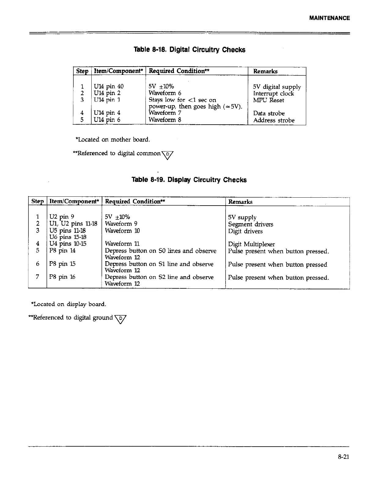
Table 8-18. Digital Circuitry Checks
ste
:
I
3
4
5
1
6
I 7
Step 1 Item/Component* 1 Required ConditknP
I I
1 Remarks
I
1
u14 pin 40
2 u14 pin 2
3 IJ14pin 1
5v *lO%
Waveform 6
5V digital supply
stays low for <1 set on
Interrupt clock
MMJ Reset
foam-u& ;hen goes high (- 5V).
Data strobe
Waveform 8 Address strobe
*Located on mother board.
*Referenced to digital common D
v
Table 8-19. Display Circuitry Checks
Item/Component*
U2 pin 9
LJl, U2 pins 11-18
u5 pins 11-18
U6 oins 15-B
u4 pins 10-15
l’8 pin 14
I’8 pin I5
I’8 pin 16
Required Condition*
5v flO%
Waveform 9
Waveform 10
Remarks
5v supply
Segment drivers
Digit drivers
Waveform 11
Depress button on SO lines and observe
Digit Multiplexer
Waveform 12
Pulse present when button pressed.
Depress button on Sl line and observe
Waveform 12
Pulse present when button pressed
Depress button on 52 line and observe
Pulse oresent when button messed.
wawfolm 72
I
I
*Located on display board.
*Referenced to digital ground v
8-21