4-13
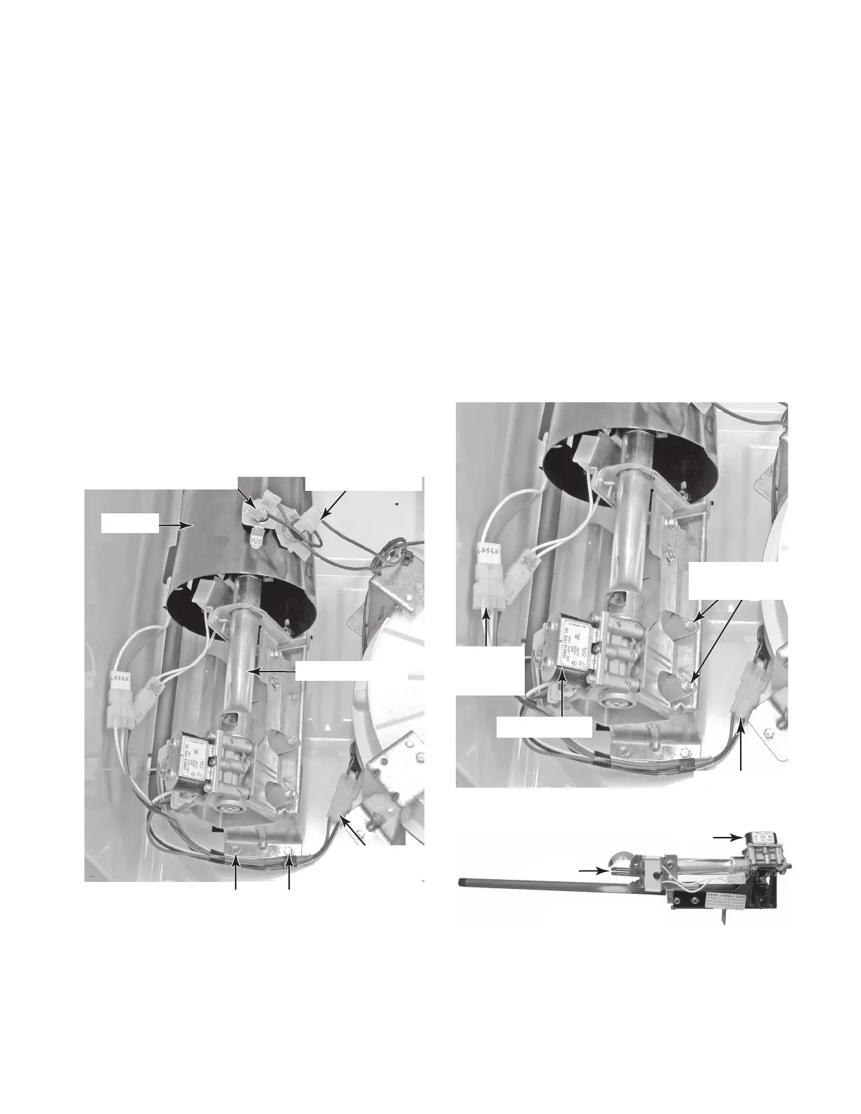
Burner Assembly
Ignitor
Coils
Burner Bracket
Screws
Flame
Sensor
Connector
Coil Assembly
7. To remove the burner assembly:
a) Disconnect the gas line from the burn-
er manifold at the left rear corner of
the dryer.
b) Disconnect the following wires from
the burner assembly components:
Connector from the flame sensor.
Coil harness connector from the main
harness.
c) Remove the two hex-head screws
from the burner bracket.
d) Pull the burner assembly forward, un-
hook the bracket tabs from the chas
-
sis slots, and remove the assembly.
•
•
Coil Harness
Connector
6. To remove the complete burner and
venturi assembly:
a) Disconnect the gas line from the burn-
er manifold at the left rear corner of
the dryer.
b) Disconnect the red & black wires from
the high-limit thermostat terminals.
c) Disconnect the blue & black wires from
the thermal cutoff terminals.
d) Disconnect the coil harness connector
from the main harness.
e) Remove the two 5/16
˝ hex-head
screws from the burner bracket.
f) Pull the burner bracket assembly for
-
ward and unhook the tabs from the
chassis slots, then remove the venturi
and burner assembly.
High-Limit Thermostat
(RD & BK Wires)
Thermal Cutoff
(BU & BK Wires)
Coil Harness
Connector
Burner Bracket Screws
Venturi
Burner Assembly
Continued on the next page.
 Loading...