6-16
P9
1
5
1
P8
P14
P2
3
1
1
6
P4
1
1
8
3
P5
P3
1
P13
1
X v
e
R
X
X
X
X
XX
N/
P
x
x-D
DD
Yed
oC e
t
aD
XX
X
-X
X
XX
O
OC
NI
ED
AM
N.O.
Black
COM
Re
d
Heater
Relay 1
Motor
Re
lay
Tan
Black-White
White
Green-Ye
llow
Brown
Blue Blac
k
Heater Relay
2
(Dual Element Model Only
)
Yellow-Red
COM
Violet
N.O.
Black
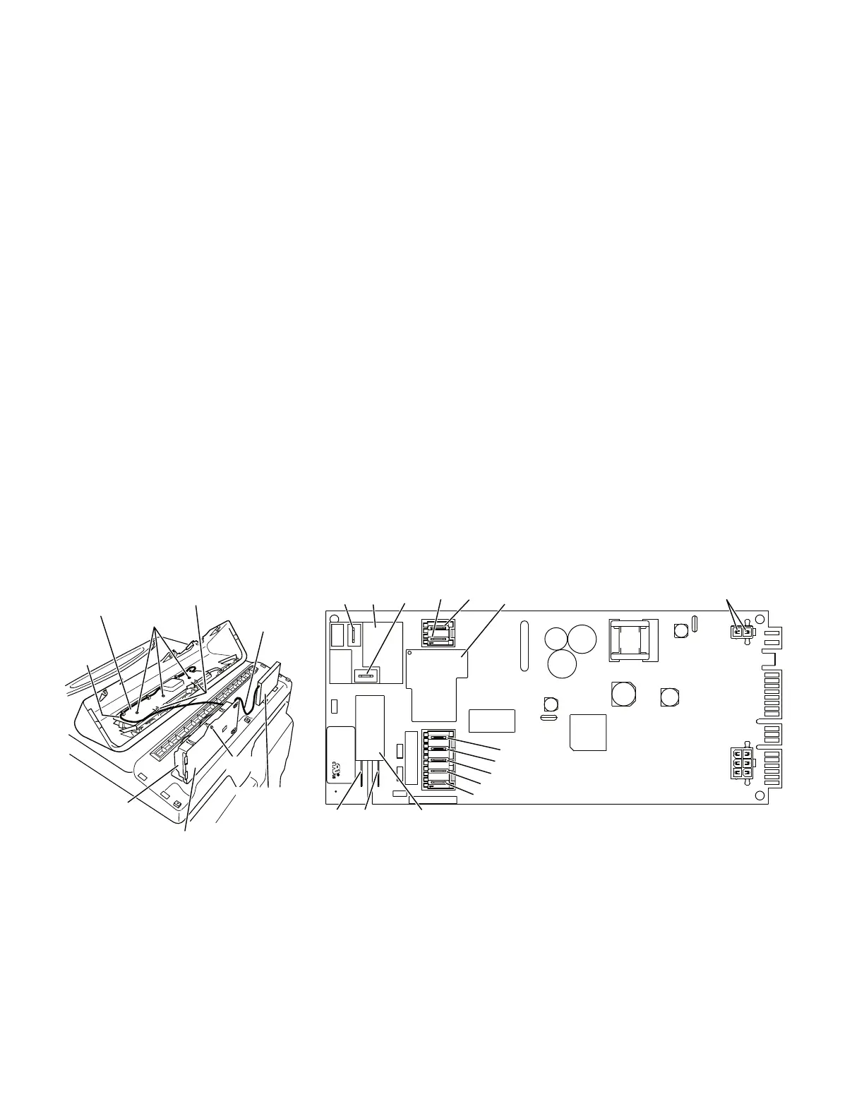
Figure 16. Machine control electronics.
ACCESSING & REMOVING THE
ELECTRONIC ASSEMBLIES
There are two electronic assemblies; the user
interface electronics, and the machine control
electronics. See Figures 15 and 16.
1. Unplug dryer or disconnect power.
2. Remove three screws from the rear of
the console assembly. Pull console to
-
wards front of dryer to hinge open and/or
remove console.
REMOVING THE MACHINE
CONTROL ELECTRONICS
3. Remove the wire connections to the
machine control assembly.
4. Remove the one screw holding the
machine control assembly to the met-
al bracket. See Figure 15.
5. Push in on the tab located on the back
of the machine control to slide it off the
bracket. See Figure 15.
Ribbon
Cable
User Interface
Assembly
Back Cover
Metal Bracket
Screw
3 Screws
Back Cover
Locking Tabs
Comm
unication
Harness
(Dual Motor
Model)
Motor Control
Electronics
Assembly
(Dual Motor
Model)
Machine Control
Electronics
Assembly
Figure 15. Locate the electronic assemblies.
REMOVING THE MOTOR CONTROL
ELECTRONICS (DUAL MOTOR MODELS)
3. Remove the wire connections to the
motor control assembly. See Figure 15.
4. Remove the two screws holding the
motor control electronics assembly to
the dryer top.
REMOVING THE USER
INTERFACE ASSEMBLY
3. Remove the wire connections from the
user interface assembly, including the
P5 ribbon cable. See Figure 15.
4. Remove the cycle selector knob from
the front of the console by firmly pull
-
ing on it or carefully prying straight up
-
ward.
5. The user interface assembly is held
to the console insert panel by three
screws and two locking tabs. After the
screws are removed, lift each of the
locking tabs to remove the back cover
of the user interface assembly. See
Figure 15.
 Loading...