1 BASIC FUNCTIONS
FUNC (K)/Ver. 1.01 Confidential Contents Index 3
1.3 Transmit and Receive
Frequency
This is a frequency pair used for transmitting and
receiving data.
A transmit frequency and a receive frequency can be
configured for each channel by using KPG-101D.
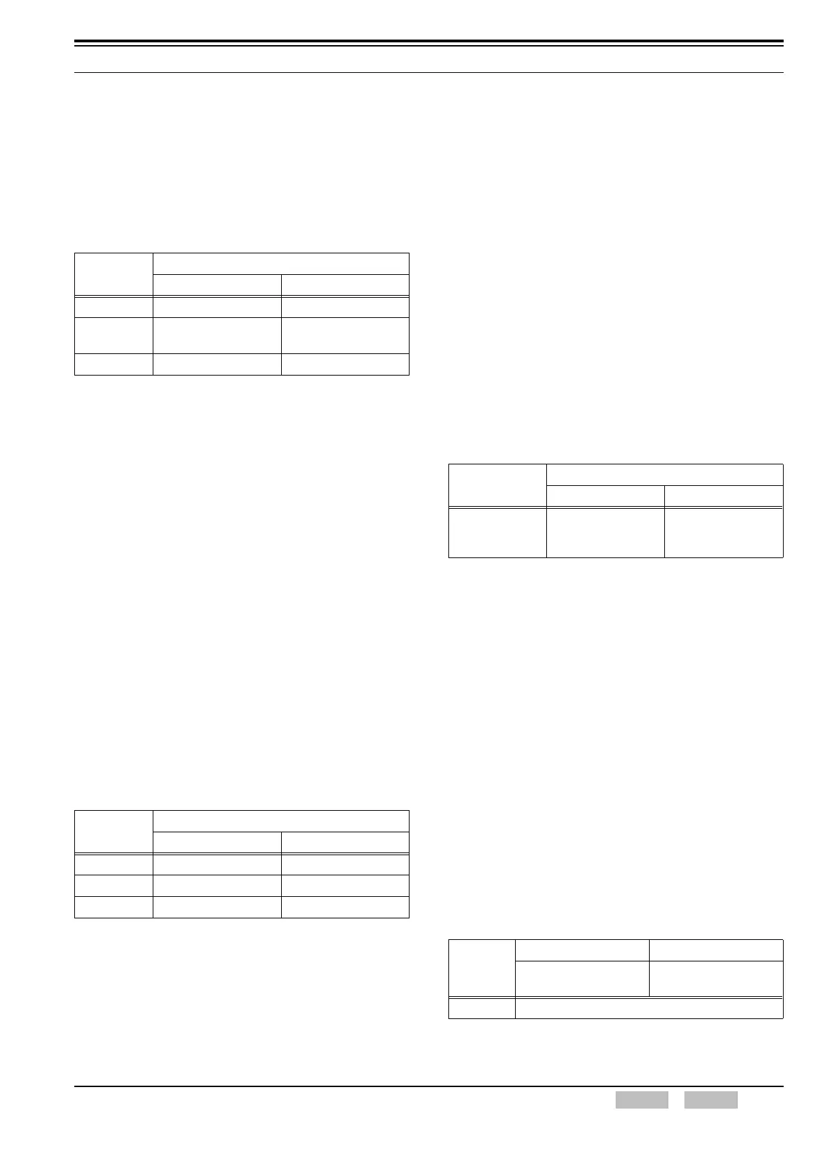
Table 1-2 Transmit/ Receive Frequencies and Step Sizes
Configuration using KPG-101D
• Configuring Transmit and Receive Frequency for
each channel (Refer to FPRG 6.4.3 Receive
frequency and 6.4.4 Transmit frequency.)
• Configuring Transmit and Receive Frequency for
the Home Repeater (Refer to FPRG 6.5.3 Receive
Frequency, 6.5.4 Transmit Frequency.)
1.4 Transmit Power
Low can be configured for the transmit power to conserve
battery power if a repeater or the receiving party is
nearby. Using low transmit power extends the operating
time of the transceiver.
Transmit power can be configured for each CH/GID using
KPG-101D.
Transmit Power can be configured using the Low
Transmit Power key.
Table 1-3 Transmit Power: Low/ High
Note: The transmit power cannot be switched to High Transmit
Power even if the Low Transmit Power key is pressed
while on CH/GIDs configured for Low Transmit Power. In
this case, the transceiver emits the Key-entry Error Tone.
Configuration using KPG-101D
• Configuring the Transmit Power (Low or High) for
each channel (Refer to FPRG 6.4.9 Transmit
Power.)
• Configuring the Transmit Power (High or Low) for
each Group ID (Refer to FPRG 6.6.6 Transmit
Power.)
• Assigning functions to the Selector and PF keys
(Refer to FPRG 6.8 Key Assignment.)
1.5 Channel Spacing
Channel Spacing is the bandwidth used for
communication.
Channel Spacing can be configured for each channel
using KPG-101D.
Table 1-4 Channel Spacing: Wide/ Narrow
Configuration using KPG-101D
• Configuring the Channel Spacing (Wide or Narrow)
for each channel (Refer to FPRG 6.4.10 Wide/
Narrow.)
• Configuring the Channel Spacing (Wide or Narrow)
for each repeater (Refer to FPRG 6.3.3 Wide/
Narrow.)
1.6 Squelch Level
Squelch Level determines the received signal level
necessary for output to be heard from the speaker.
When the received signal is weak, configure a lower
Squelch level value. Increase Squelch Level to block
speaker output of unwanted weak signals.
Table 1-5 Squelch Level
Model
Transmit and Receive Frequency
Range [MHz] Step [kHz]
TK-2170 136 to 174 2.5/ 5.0/ 6.25/ 7.5
TK-3170
400 to 430
450 to 490
5.0/ 6.25
TK-3173 450 to 490 5.0/ 6.25
Model
Transmit Power [W]
Low High
TK-2170 1 5
TK-3170 1 4
TK-3173 1 4
Model
Channel Spacing [kHz]
Wide Narrow
TK-2170/
TK-3170/
TK-3173
25 12.5
Range
01 to 9
Mute function is
completely disabled.
Shallow (Small) to
Tight (Large)
In steps of 1
 Loading...