Seffing up fhe sysfem
Make connections as shown in the following pages.
When connecting the related system components, be sure
to refer to the instruction manuals supplied with the compo-
nents you are connecting.
Do
not connect the power cord to a wall outlet until all
connections are completed.
Notes
1 Be sure to ltisert all connectIon cords securely if their connections are
Imperfect, socrrnd n?ay not be produced or there WIII be no/se inference
2 Be sure to remove the power cord from the AC outlet before plugging
or unplugging any connectIon cords Plugginglunplugglng connection
cords without dlsconnectlng the power cord can cause malfunctions
and (may darnage the unit
3 Do not connect power cords from components whose power con-
sumptlon 1s larger than what IS indicated on the AC outlet at the rear
of this unit
Analog connections
Audio connectIons are tmade using RCA pin cords These cables transfer
stereo audio siglnal in an “analog” form. This means the audio slgnal
corresponds to the actual audio of two channels These cables usually
have 2 plugs on each end, one red for the right channel and one white for
the left channel. These cables are usually packed together with the
source tInIt, or are available at your local electronics retailer
though all connections Ihave been made properly, reset tiie micro-
computel ieferrlng to “In case of difficulty”
CAUTIO~II
Be sure to adhere to the following, or proper ventilation will be
blocked causing damage or fire hazard.
l
Do not place any objects Impairing heat radlatlon onto the top of the
unit
l
Leave solve space around the unit (from rhe largest outsIde
dlmenslon lncludll?g plolectlon) equal to or greater than, shown
below
Top panel : 50 cm Side panel : 10 cm Back panel : 10 cm
Input mode settings
CD/DVD, VIDEO 2 and DVD/GCH Inputs each Include jacks for dIgItal
audio Input and analog audio Input.
You must select beforehand which type of Input IS to be used for each
connected component.
The initial factory settings for audio signal playback for CWDVD.
DVD/GCH and VIDEO 2 are full auto.
To use the analog audio Input for playback Instead (If, for example, you
have connected a VCR to the VIDEO2 Input), you must set the Input
mode for the corresponding Input to the analog mode.
After completing connections and turning on the receiver, follow the
steps below.
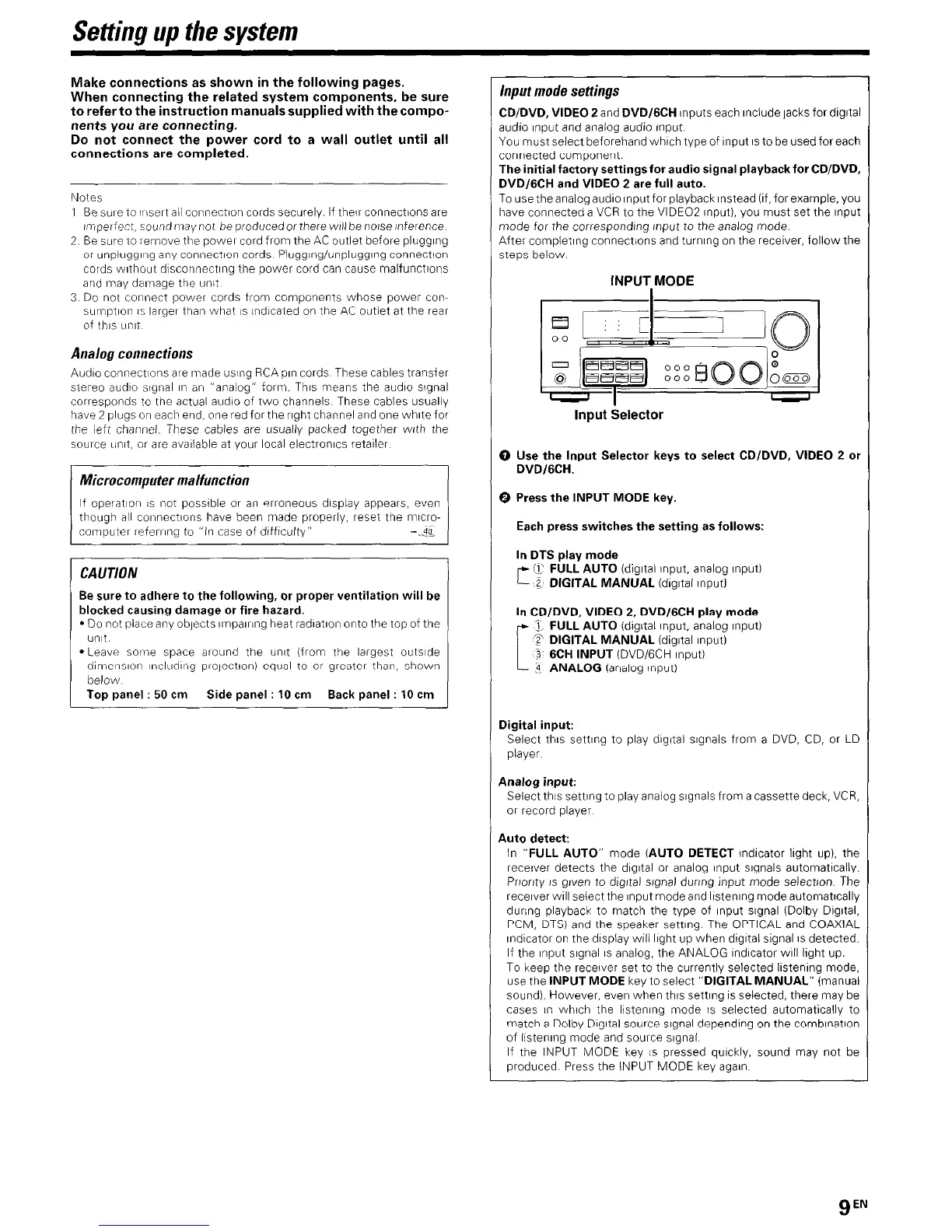
INPUT,MODE
Input Selector
0 Use the Input Selector keys to select CD/DVD, VIDEO 2 or
DVDIGCH.
0 Press the INPUT MODE key.
Each press switches the setting as follows:
In DTS play mode
f7 FULL AUTO (digItal Input, analog Input)
r--
z DIGITAL MANUAL (dlgltal Input1
In CD/DVD, VIDEO 2, DVD/GCH play mode
3, FULL AUTO (dIgItal Input, analog Input)
T DIGITAL MANUAL (digital Input)
3 6CH INPUT (DVD/GCH Input)
3 ANALOG (analog input)
Digital input:
Select this setllng to play digital signals from a DVD, CD, or LD
player
Analog input:
Select this setting to play analog signals from a cassette deck, VCR,
or record player
Auto detect:
In “FULL AUTO” mode (AUTO DETECT lndlcator light up). the
receiver detects the dIgItal or analog Input signals automatically.
Pnonty IS given to dIgItal slgnal during Input mode selectton. The
receiver WIII select the Input mode and llstenlng mode automatlcally
during playback to match the type of Input slgnal (Dolby DIgItal.
PCM, DTS) and the speaker setting. The OPTICAL and COAXIAL
Indicator on the display will light up when digltal signal IS detected.
If the Input slgnal IS analog, the ANALOG Indicator WIII light up.
To keep the receiver set to the currently selected listening mode,
use the INPUT MODE key to select “DIGITAL MANUAL” (manual
sound) However, even when this setting IS selected, there may be
cases I” which the listening mode IS selected automatically to
match a Dolby DIgItal source slgnal depending on the comblnatlon
of listening mode and source slgnal
If the INPUT MODE key IS pressed quickly, sound may not be
produced. Press the INPUT MODE key agaIn
gEN
 Loading...