TP-6196 10/09 101Section 7 Disassembly/Reassembly
Section 7 Disassem bly/Rea ssembly
This section provides instructions for the disassembly
and reassembly of the generator set alternator. Before
beginning the generator disassembly or reassembly
procedure, carefully read all safety precautions at the
beginning of this manual.
7.1 Disas sembly
The disassembly procedure provides important
information to minimize disassembly time and indicates
where special configurations exist, which may require
taking notes.
The engine and generator set may use both American
Standard and metric hardware. Use the correct size
tools to prevent rounding of the bolt heads and nuts.
1. Remove the generator set from service and
remove the generator set enclosure.
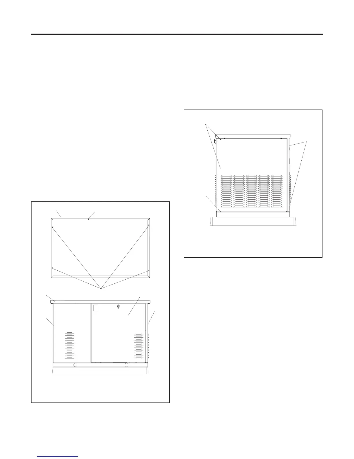
a. Remove the enclosure service-side door. See
Figure 7-1.
tp6196
4
1. Roof
2. Roof locating pin
3. Roof screws (4 ea.)
4. Service-side door
5. Front panel (air intake end)
6. Rear panel (exhaust end)
6
1
5
1
3
2
Figure 7-1 Generator Set Weather Housing
b. Place the generator set master switch in the
OFF position.
c. Remove 4 roof screws. Lift the roof up and off.
See Figure 7-1.
d. Remove 5 screws to remove the front panel.
Remove the plastic caps to access the 2 side
screws. See Figure 7-2.
tp6196
1. Screws (2 ea.)
2. Plastic caps (2 ea.) (remove to access screws)
3. Screw (1 ea.) (access from inside the enclosure)
1
3
2
Figure 7-2 Front Panel Mounting Screw Locations
e. Disconnect power to the battery charger.
f. Disconnect the generator set engine starting
battery, negative (--) lead first.
g. Turn off the fuel supply to the generator set.

 Loading...


