TP-6196 10/09 77Section 6 Component Testing and Adjustment
6.4 Main Field (Rotor)
The two-pole rotor creates the magnetic field needed to
produce alternating current in the stator windings.
Before testing, inspect the rotor for visible damage to
pole shoes, insulation, exposed coil windings, and slip
ring surfaces. Rotate the bearing to check for wear, heat
discoloration, or noise.
Rotor Continuity and Resistance Tests
Hazardous voltage.
Can cause severe i njury or death.
Operate the generator set only when
all guards and electrical enclosures
are in place.
Moving parts.
WARNING
High voltage test. Hazardous voltage can cause severe
injury or death. Follow the instructions of the test equipment
manufacturer when performing high-voltage tests on the rotor
or stator. An improper test procedure can damage equipment
or lead to generator set f ailure.
Grounding electrical equipment. Hazardous voltage can
cause severe injury or death. Electrocution is possible
whenever electricity is present. Ensure you comply with all
applicable codes and standards. Electrically ground the
generator set, transfer switch, and related equipment and
electrical circuits. Turn off the main circuit breakers of all
power sources before servicing the equipment. Never contact
electrical leads or appliances when standing in water or on wet
ground because these conditions increase the risk of
electrocution.
Rotor Test Procedure
1. Place the generator set master switch in the OFF
position.
2. Disconnect power to the battery charger.
3. Disconnect the generator set engine starting
battery, negative (--) lead first.
4. Remove the brush cover from the alternator end
bracket.
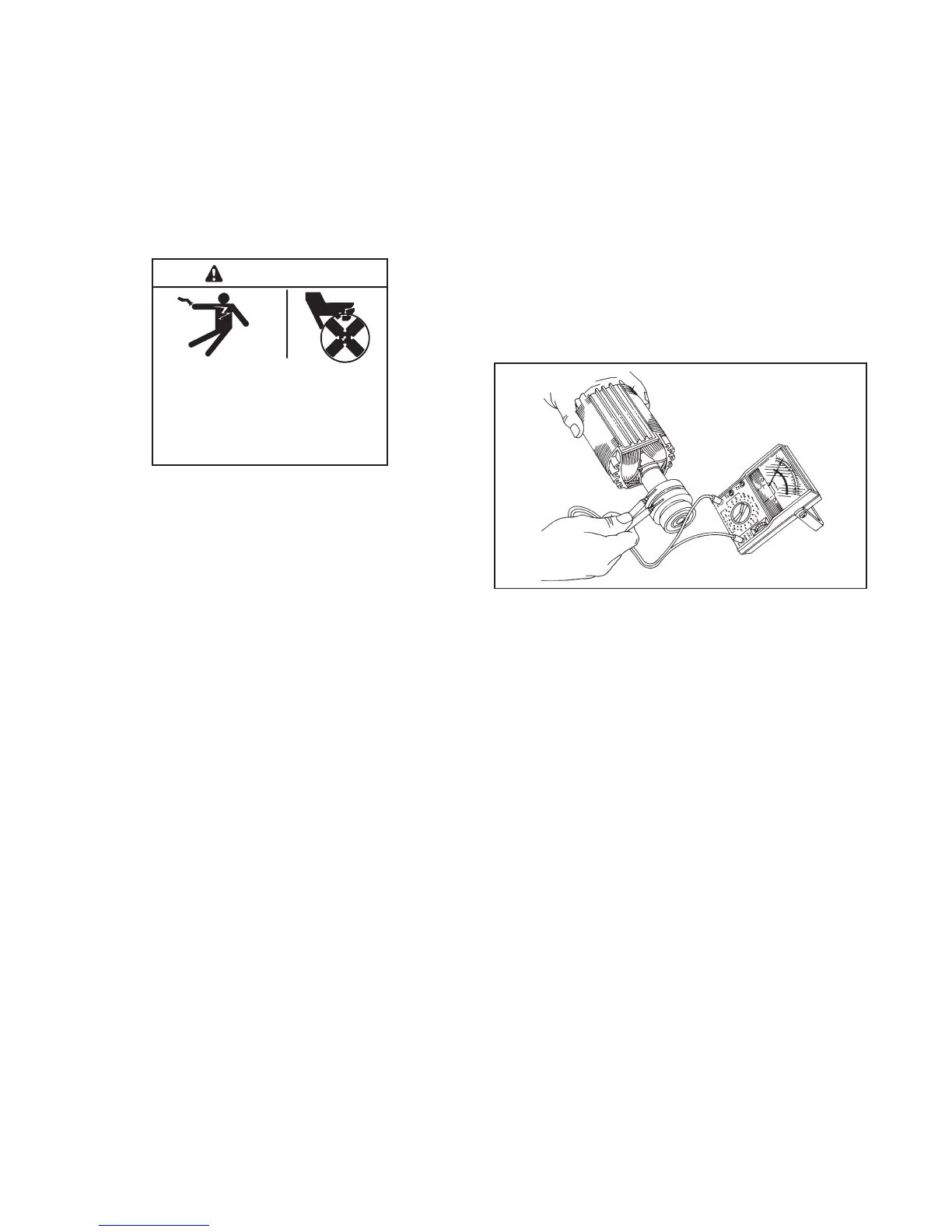
5. Check the rotor for continuity and resistance.
Raise the brushes from the slip rings while
performing ohmmeter tests. Measure the rotor
resistance (ohms) between the two slip rings; see
Figure 6-9. See Section 1.6, Alternator
Specifications, for rotor resistance readings. If the
resistance readings are low, perform a
megohmmeter test on rotor as described in the
next step.
Note: Because ohmmeter accuracy varies,
resistance readings are approximate. Take
readings at room temperature.
2-221
R13929-7
Figure 6-9 Rotor Resistance Check
6. Perform a megohmmeter test to determine
whether the rotor is shorted to ground.
a. Raise and secure the brushes away from the
slip rings by inserting a retaining wire in the
brush holder hole.
b. Using a megohmmeter, apply 500 volts DC to
one rotor slip ring and the rotor poles or shaft.
Follow the instructions of the megohmmeter
manufacturer when performing this test.
Note: A reading of approximately 500 kOhms
(1/2 megohm) or higher indicates a
good rotor.

 Loading...


