TP-6196 10/09 53Section 5 ADC-RES and DC-RET Controller
Section 5 ADC-RES and DC-RET Controller
5.1 Introduction
This section covers operation, configuration,
adjustment, and replacement of the ADC-RES and
DC-RET controllers. See Section 3 for troubleshooting
procedures.
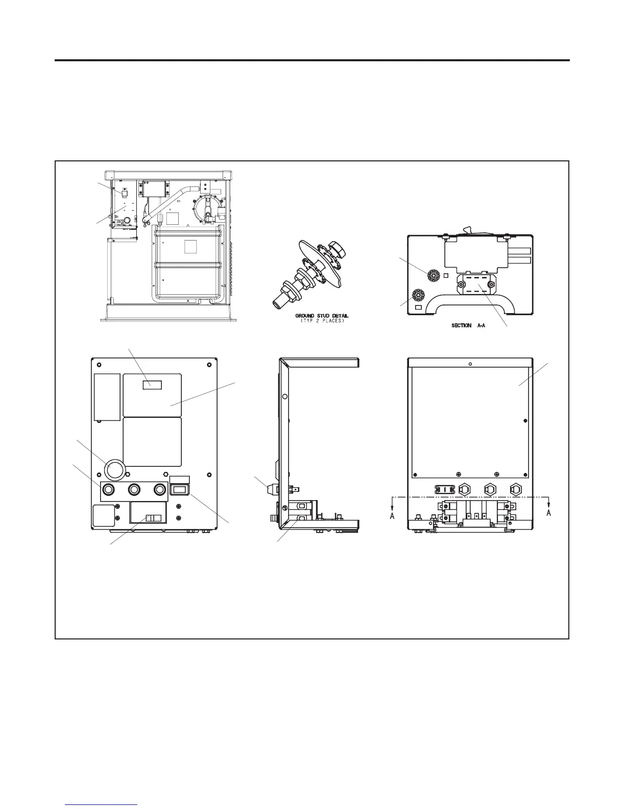
See Figure 5-1 for the controller location.
1. Controller display
2. Keypad (ADC-RES only; see Figure 5-2)
3. Generator set master switch (RUN-OFF/RESET-AUTO)
4. Line circuit breaker (load connection)
5. Fuses F1, F2, and F3
6. Serial port for communication connection (remove plug to access)
GM57149
10
4
4
3
6
9
12
5
1
2
5
7
Front View
7. Logic board
8. Optional relay board location
9. L0 stud
10. Ground stud
11. Start relay
12. SCR module
11
8
Figure 5-1 Controller Components

 Loading...


