TP-6196 10/0982 Section 6 Component Testing and Adjustment
6.7.5 Voltage Connections, 3-Phase
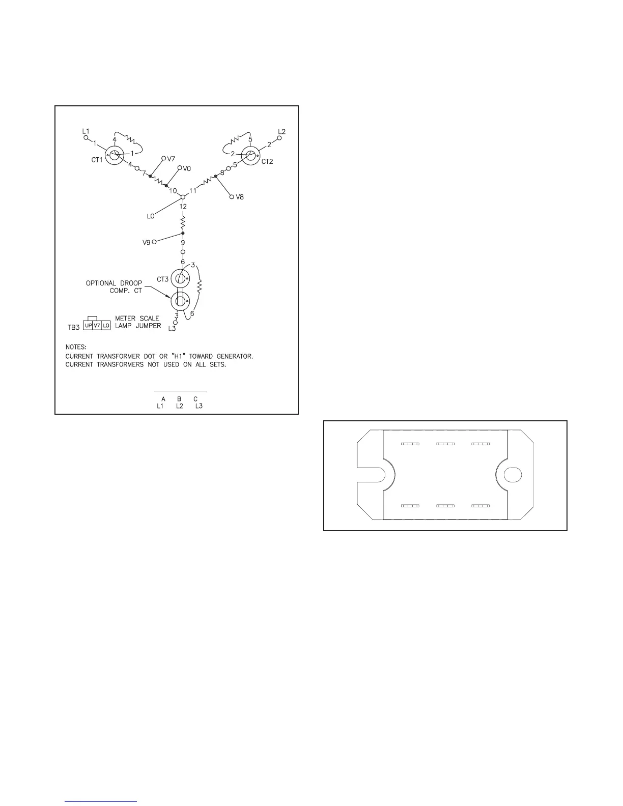
Three-phase generator sets are connected for
230/400 Volts, 50 Hz. See Figure 6-17 for the factory
connections. The generator sets are not reconnectable.
ADV--5875
PHASE ROTATION
Figure 6-17 3-Phase Configuration
6.8 S ilicon Controlled Rectifier
Module
The silicon controlled rectifier (SCR) module works with
the ADC-RES to regulate the output voltage. The
ADC-RES monitors generator output voltage and
adjusts the excitation current to the rotor through the
SCR module. The SCR module location is shown i n
Figure 4-1.
The SCR module is powered through stator leads 55
and 66 connected to SCR terminals AC1 and AC2.
Leads G connected to terminals G1 and G2 provide the
controller signal. Leads FP and FN connected to the
positive (+) and negative (--) SCR terminals provide
excitation current to the rotor. See Figure 6-18 and the
wiring diagrams in Section 8.
The SCR m odule is protected by a 20-amp fuse (F1) in
lead 55 on the controller. Check the fuse and replace it,
if blown.
In the case of output voltage problems, check the
controller configuration and settings. Then test the SCR
module using the following procedure.
Note: If it is necessary to replace the SCR module, be
sure to apply thermal compound to the back of the
module to prevent overheating. Thermal
compound is provided with the SCR module
replacement kit.
GM28483
G1
G2AC2
AC1 --
+
Figure 6-18 Silicon Controlled Rectifier (SCR)
Module

 Loading...


