TP-6196 10/09 35Section 4 ADC 2100 and DC 2200 Controllers
Section 4 ADC 2100 and DC 2200 Controllers
4.1 Introduction
This section covers operation, configuration,
adjustment, and replacement of the ADC 2100 and
DC 2200 controller. See Section 3 for troubleshooting
procedures.
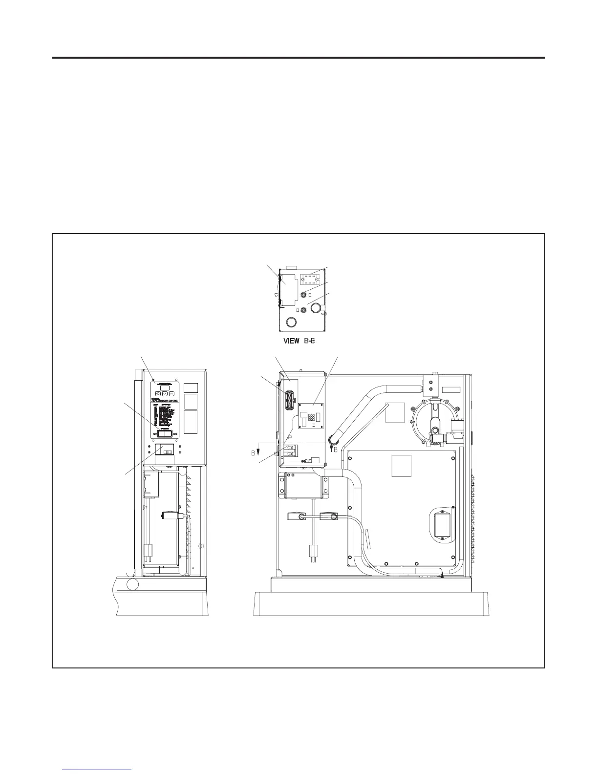
See Figure 4-1 for the locations of the controller and
related components. Section 4.2 describes the
controller keypad and display. Section 4.3 describes the
sequence of operation and faults are described in
Section 4.4. Controller configuration and adjustment
are covered in Section 4.5.
A sil icon controlled rectifier (SCR) module works with
the controller to regulate the output voltage. See
Section 6.8.
A relay interface board (RIB) is used with the ADC
controller. Section 4.8 describes the standard and
optional RIBs.
1
GM29253
1. Controller
2. SCR module
3. Ground stud
4. L0 stud
5. Relay interface board (RIB)
6. Line circuit breaker (load connection)
7. Engine harness-to-controller connection
8. Generator set master switch
3
7
1
5
6
6
8
1
4
2
Figure 4-1 Advanced Digital Control (ADC 2100)

 Loading...


