TP-6196 10/0948 Section 4 ADC 2100 and DC 2200 Controllers
4.7 Master Switch
The generator set master switch is a three-position
(RUN\OFF/RESET\AUTO) rocker switch. The leads
connecting to the master switch are labeled RUN, VBAT,
and AUTO. Check that the three pink connectors are
connected to the terminals on the back of the switch as
shown in Figure 4-14. Be careful not to reverse the RUN
and AUTO leads.
4.8 Re lay Interface Board (RIB)
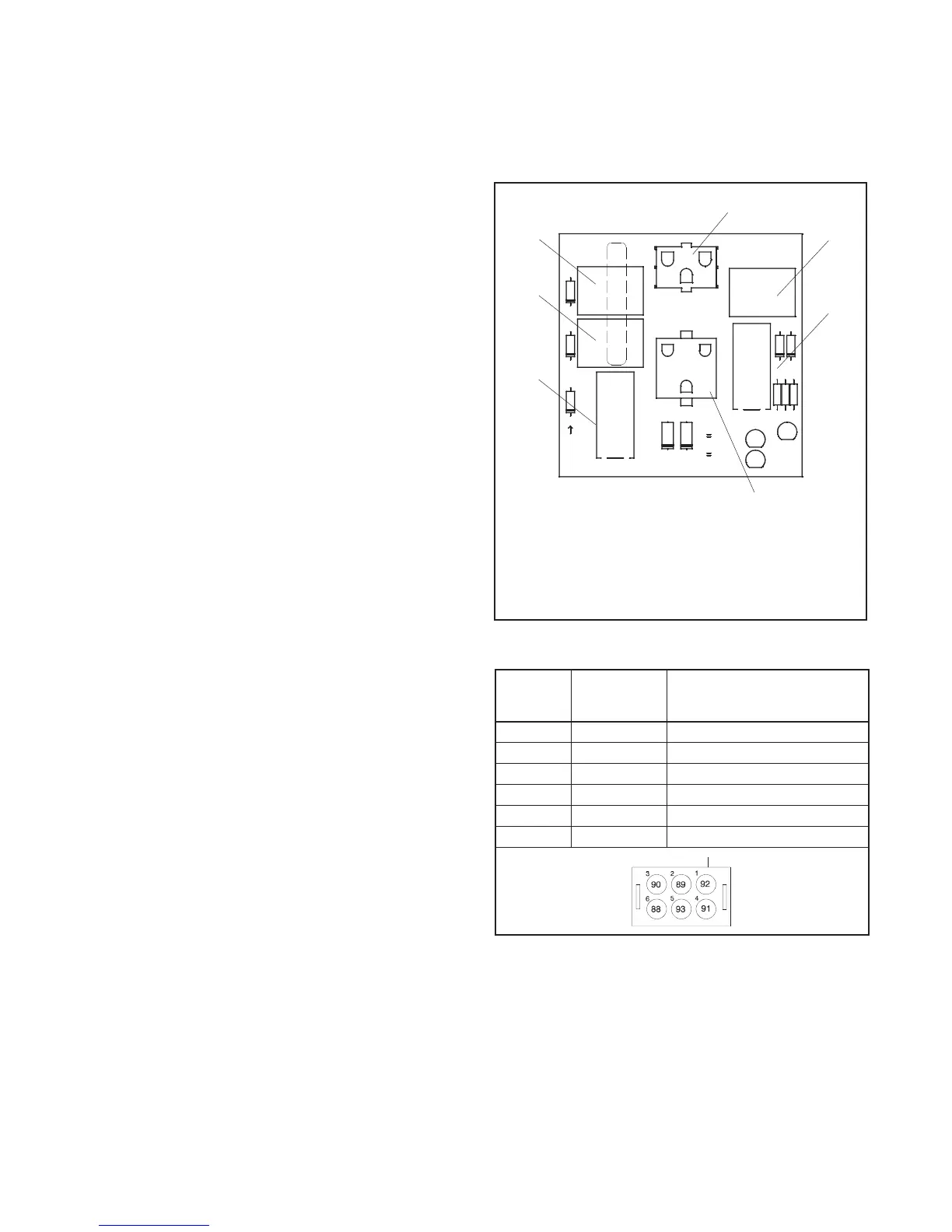
The standard relay interface board (RIB) contains the
K2 crank, K3 flash, and K5 run relays. Three LEDs
indicate relay operation. See Figure 4-15.
Refer to the schematic diagram in Section 8 for the
standard relay board connections.
The RIB is protected by a 10 amp fuse (F2) located in the
wiring harness. If the fuse blows repeatedly, disconnect
the board loads one at a time to identify the cause of the
blown fuse:
! Lead 70A at the fuel valve
! Lead IGN at the ignition module
! Lead 71A at the starter relay
! Leads FP and FN at the rotor
Repair or replace the component causing the blown
fuse.
If fuse continues to blow and disconnecting components
did not identify the cause, remove the leads from the
P14 connector using a pin pusher, part #241918 (large)
or 241919 (small). If replacing the leads does not solve
the problem, replace the RIB.
The individual relays are not replaceable. If one or more
relays are faulty, replace the entire RIB.
To replace the RIB:
1. Disconnect P14 and the brush leads FP and FN.
2. Pull the board straight off the mounting stand-offs.
3. Snap the new board onto the stand-offs and
reconnect P14 and the brush leads.
The generator set may be equipped with an optional
RIB, which contains the K4 auxiliary run relay and K1
common fault relay in addition to the standard relays.
The optional relay board kit includes a wiring harness for
connection of customer equipment to the K 1 and K4
relays. See Figure 4-16 for optional relay connections.
4
GM29779-A
1. K1 common fault relay (optional)
2. K2 crank relay (standard)
3. K3 flash relay (standard)
4. K4 auxiliary run relay (optional)
5. K5 run relay (standard)
6. P14, engine harness connection (standard)
7. P13, connection to optional relay harness (optional)
FLASH
K3
VBAT
D3D1 D2
K1
FLASH
LED2
CRANK
LED3
D4
D5
T2
FP
9
FN
T1
7
RUN
R
R
R
LED1
R1
R2
R3
K4
46
P13
P14
K2
CRANK
3
K5
1
RUN
FAULT
COMMON
3
1
D7
D6
AUX
RUN
5
1
2
3
7
6
Figure 4-15 Relay Board
Harness
Lead
Number
Connector
Pin Number
Connection
88 6 Common fault normally open
89 2 Common fault common
90 3 Common fault normally closed
91 4 Run relay normally open
92 1 Run relay common
93 5 Run relay normally closed
Figure 4-16 Optional Common Fault and Run Relay
Board Harness Connections

 Loading...


