TP-6196 10/0974 Section 6 Component Testing and Adjustment
Grounding electrical equipment. Hazardous voltage can
cause severe injury or death. Electrocution is possible
whenever electricity is present. Ensure you comply with all
applicable codes and standards. Electrically ground the
generator set, transfer switch, and related equipment and
electrical circuits. Turn off the main circuit breakers of all
power sources before servicing the equipment. Never contact
electrical leads or appliances when standing in water or on wet
ground because these conditions increase the risk of
electrocution.
Short circuits. Hazardous voltage/current can cause
severe injury or death. Short circuits can cause bodily injury
and/or equipment damage. Do not contact electrical
connections with tools or jewelry while making adjustments or
repairs. Remove all jewelry before servicing the equipment.
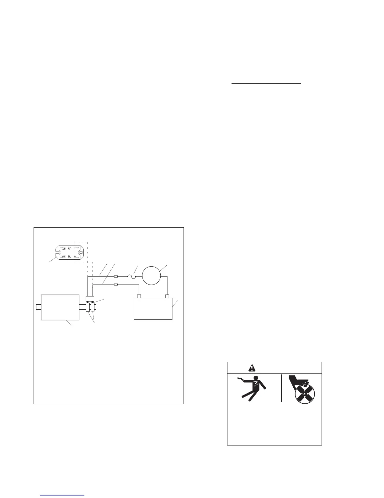
Separate Excitation Procedure
Perform the following procedure to use an external
voltage source to excite the main field (rotor).
1. Disconnect the black FN and FP leads from the
alternator at the SCR module (+) and (--) terminals.
2. Connect a DC ammeter, 20-amp fuse, and a
12-volt automotive battery to the positive (FP) and
negative (FN) brush leads as shown in Figure 6-3.
Note and record the ammeter reading.
+
-
+
1
2 3 4
5
6
7
8
9
TP563274
-
1. SCR module
2. FN lead disconnected from SCR
3. FP lead disconnected from SCR
4. 10-amp fuse
5. DC ammeter
6. 12V battery
7. Brushes
8. Slip rings
9. Main field (rotor)
FP
FN
Figure 6-3 Separate Excitation Connections
Note: The approximate ammeter reading should
be the battery voltage divided by the
specified rotor resistance. See Section 1,
Specifications, for specified rotor resistance
values.
Example:
12 volts (battery voltage)
4 ohms (rotor resistance)
=
3 amps
(rotor current)
3. Start the engine and check that the ammeter
reading remains stable. An increasing meter
reading indicates a shorted rotor. A meter reading
decreasing to zero or an unstable reading
suggests a running open. Refer to Section 6.5,
Main Field (Rotor), to test the rotor. If the ammeter
reading is stable, proceed to step 4.
4. Check for AC output across the stator leads; see
Section 6.3, Stator. Compare the readings to the
AC output values shown in Section 1,
Specifications. If the readings vary considerably, a
faulty stator is likely. Refer to Section 6.3, Stator,
for further information.
5. If this test shows that the rotor and stator are in
good condition, check the wiring and fuses. Check
SCR module. See Section NO TAG, Silicon
Controlled Rectifier Module. Check the controller
settings and connections. See Section 4,
Controller Configuration and Adjustment.
6.3 Stator
The stator contains a series of coils of wire laid in a
laminated steel frame. The stator leads supply AC
voltage to the load and voltage regulator. Before testing
the stator, inspect it for heat discoloration and visible
damage to housing lead wires, exposed coil windings,
and exposed areas of frame laminations. Be sure the
stator is securely fastened to the stator housing.
Note: Disconnect all stator leads before performing all
stator tests.
Hazardous voltage.
Can cause severe i njury or death.
Operate the generator set only when
all guards and electrical enclosures
are in place.
Moving parts.
WARNING

 Loading...


