TP-6196 10/09 73Section 6 Component Testing and Adjustment
Section 6 Com pone nt Testing a nd Adjus tment
6.1 Theory of Operation
These generator sets utilize a rotating-field alternator to
produce AC voltage. Upon activation of the generator
master switch, DC current from the battery magnetizes
the rotor (field). When the magnetized rotor rotates
within the stator windings, an electrical voltage develops
within the stator. As engine speed and generator output
increase, the SCR module feeds rectified stator output
current to the rotor through the brushes/slip rings to
increase the strength of the rotor field. As the rotor field
increases in strength, generator output also increases.
The ADC controller monitors the generator output
voltage through leads 11 and 44 (single-phase) or leads
V7, V8, and V9 (three-phase) and adjusts the DC
current from the SCR module to the rotor to meet load
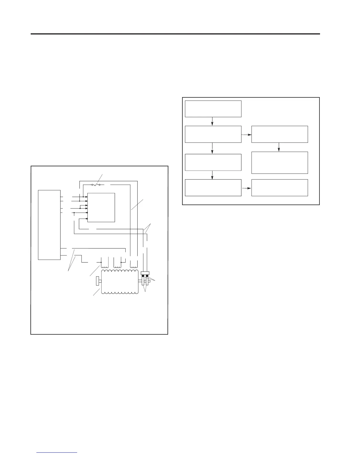
requirements. See Figure 6-1.
FP
11
34
55
2 1
44
7
5
2
8
6
TP6196
1. Fuse
2. Power lead (55)
3. Excitation to rotor
4. Brushes
5. Slip rings
6. Main field (rotor)
7. Stator windings
8. Sensing leads (11--44)
66
11
1
ADC
Controller
SCR
4
(--)
(+)
AC1
AC2
G1
G2
44
66
66
55
55
G
F+
FN
FP
FN
3
Figure 6-1 Single-Phase Generator Schematic
6.2 S eparate Excitation
To determine the cause of no or low AC output, refer to
the troubleshooting flow chart in Figure 6-2. Before
beginning the test procedures, read all safety
precautions at the beginning of this manual. Many of the
test procedures include additional safety precautions.
No Generator Output
Separate E xcit ation
Output within
Specifications
Check Rotor
Check Wiring, Fuses,
SCR Module and
Controller
Check St ator
TP563273
Erratic or No Output
Figure 6-2 Generator Troubleshooting
Check the condition of the alternator fuse before
performing the separate excitation procedure. The
inline fuse is located in lead 55 of the wiring harness or
on the junction box panel near the cotnroller. See
Figure 6-1. If the fuse is not blown, use the following
procedure to separately excite the generator using an
external voltage source (a 12-volt automotive battery).
Separately exciting the generator can identify faulty
voltage regulation by the ADC controller or reveal a
running fault in the rotor and/or stator. An external
power source duplicates the role of the voltage regulator
and excites the generator field (rotor). A generator
component that appears to be in good condition while
stationary may exhibit a running open or short circuit
while moving. Centrifugal forces acting on the windings
during rotation cause a broken circuit to open, or
increasing temperatures cause the insulation to break
down, resulting in a running fault. If this test shows that
the rotor and stator are in good condition, test the
voltage regulation using the tests in Section 6.13.

 Loading...


