TP-6805 8/15 15Section 1 Specifications
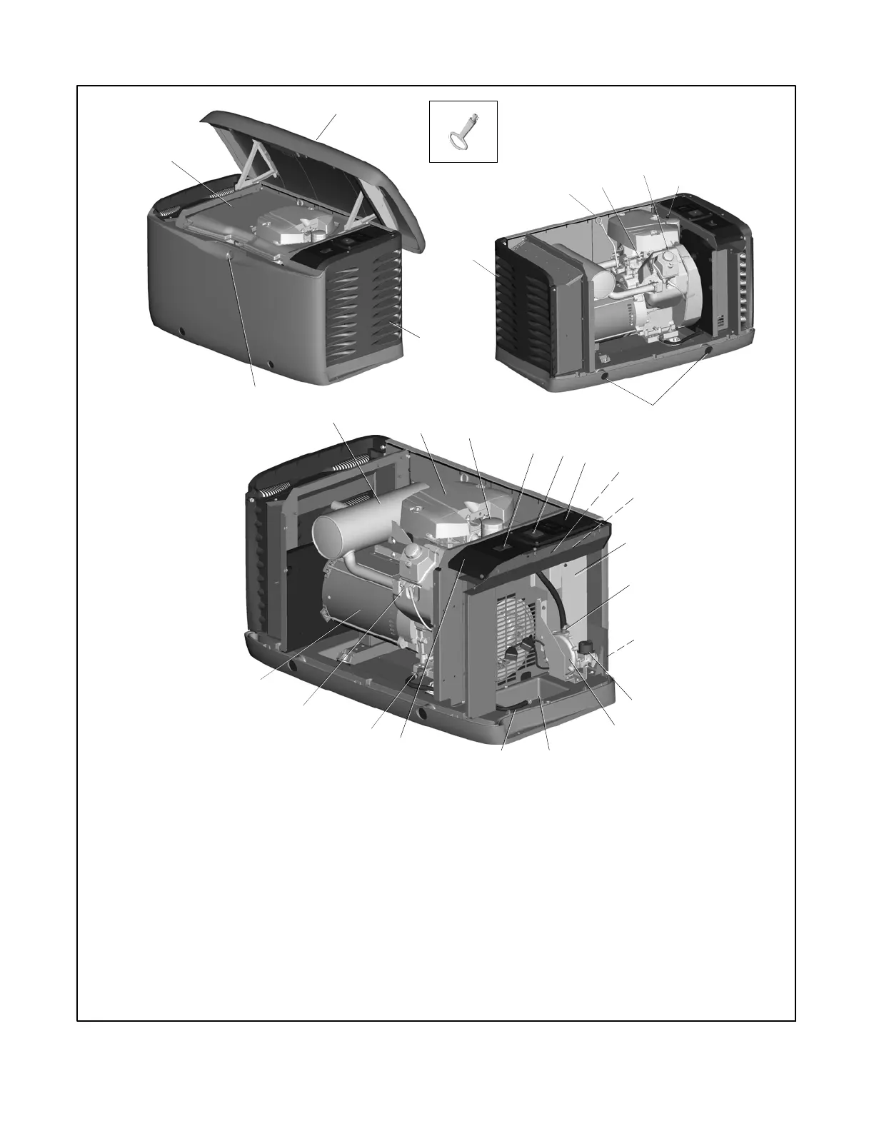
1.7 Service Views
23
22
25
1
3
12
13
20, 21
24
ADV-8424
15
14
26
1. Hinged inner cover
2. Hinged roof
3. Air intake
4. Lock
5. Key, provided with generator set
6. Exhaust outlet
7. Oil check (dipstick)
8. Governor assembly
9. Oil fill
10. 120 VAC receptacle for optional carburetor heater
11. Lifting holes
12. Muffler
13. Air cleaner
14. Oil filter
15. Line circuit breaker
16. Mini-breaker and USB connector (for firmware updates)
17. RDC2 or DC2 controller (original controller shown)
18. Alternate mini-breaker location (See Section 5.4)
19. Starter relay (below controller)
20. Field-connection terminal block (behind panel)
21. Ignition timing leads
22. Fuel block (early 14 kW models only) or fuel orifice location
(inside hose fitting)
23. Fuel inlet
24. Fuel solenoid valve
25. Fuel regulator assembly
26. Engine starting battery location (battery purchased separately)
27. Oil drain hose
28. Nameplate location
29. Oil drain valve
30. Spark plugs
31. Alternator
27
17
29
16
28
6
11
7
9
2
4
5
8
31
30
19
ENCLOSURE
PANELS REMOVED
TO SHOW DET AIL
18
10
Figure 1-1 Service Views, 14/20RESA(L)

 Loading...


