TP-6805 8/1594 Section 6 Component Testing and Adjustment
6.2 Alternator Excitation
Hazardous voltage.
Can cause severe injury or death.
Operate the generator set only when
all guards and electrical enclosures
areinplace.
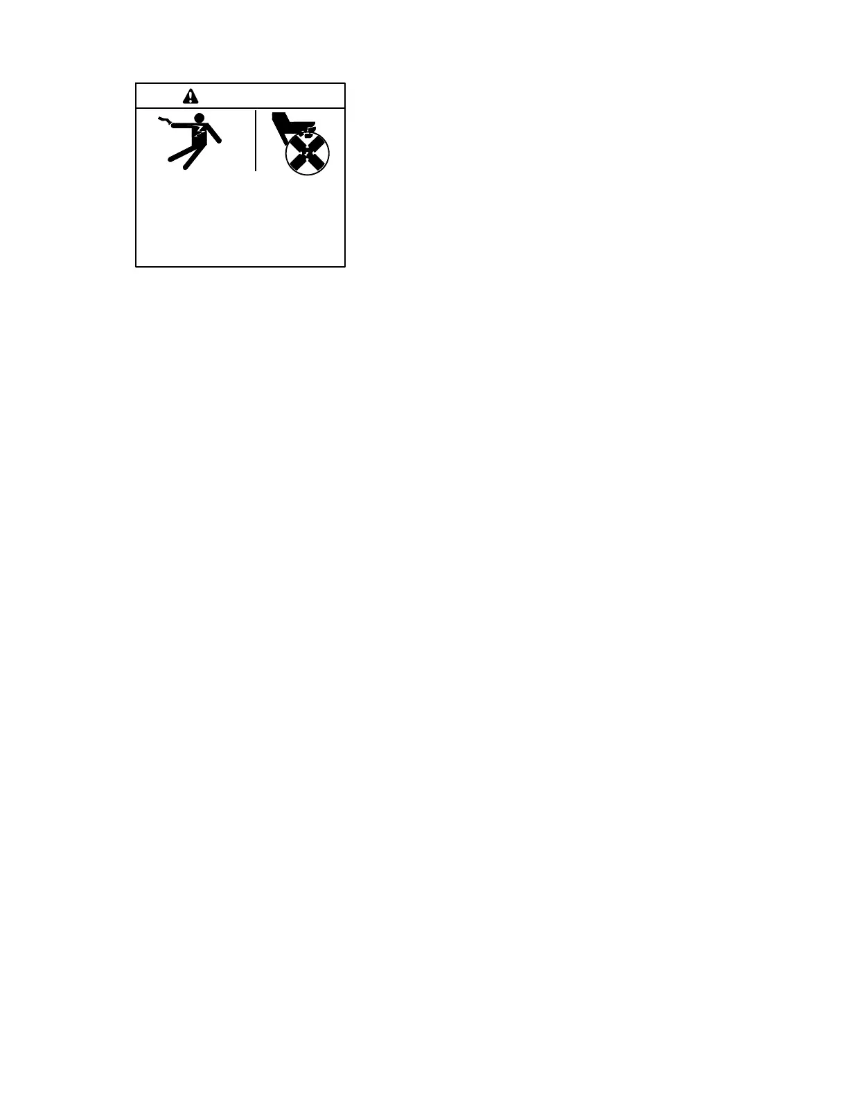
Moving parts.
WARNING
Testing live electrical circuits. Hazardous voltage or
current can cause severe injury or death. Have trained and
qualified personnel take diagnostic measurements of live
circuits. Use adequately rated test equipment with electrically
insulated probes and follow the instructions of the test
equipment manufacturer when performing voltage tests.
Observe the following precautions when performing voltage
tests: (1) Remove all jewelry. (2) Stand on a dry, approved
electrically insulated mat. (3) Do not touch the enclosure or
components inside the enclosure. (4) Be prepared for the
system to operate automatically.
(600 volts and under)
Short circuits. Hazardous voltage/current can cause
severe injury or death. Short circuits can cause bodily injury
and/or equipment damage. Do not contact electrical
connections with tools or jewelry while making adjustments or
repairs. Remove all jewelry before servicing the equipment.
6.2.1 No to Low Voltage Operation
This section covers the operation of the alternator
excitation and troubleshooting information for low or no
voltage output.
Before beginning the test procedures, read all safety
precautions at the beginning of this manual. Many of the
test procedures include additional safety precautions.
After crank disconnect, controller will disengage the
flash relay when the AC output of the generator reaches
1/4 of the output voltage. At this level, the output on the
auxiliary windings should have reached a level sufficient
to self-excite the alternator rotor field. If the output
voltage does not exceed 1/3 of rated voltage, the
generator is only producing voltage using the flash relay.
To further isolate the cause of this failure:
1. Check the condition of the alternator circuit
breaker. The circuit breaker is located in the service
access area on the controller. If this breaker is
open, the auxiliary winding current will not be able
to reach the field and the field will only be supplied
by the flash relay. If the breaker is tripped, stop the
generator, disconnect P2 and verify no continuity
between ground and each of 55, 66, FP, FN.
2. Verify the connections for 55, 55F and 66 per
Figure 6-1.
3. Reconnect P2, start the generator and check for
voltage between 55 and 66. This voltage should
exceed 30 Volts AC when the AC output voltage is
above 60 Volts AC. If the voltage does not exceed
30 VAC, stop the generator and complete the rotor
and stator checks in Sections 6.3 and 6.4.
4. Check DC voltage between FP and FN. If this
voltage is above 20 VDC, stop the generator and
complete the rotor and stator checks in Sections
6.3 and 6.4.
5. If the auxiliary winding voltage exceeds 30 VAC
and the field voltage does not exceed 20 VDC,
replace the generator controller.
6.2.2 Erratic Voltage Regulation
Dramatic variations in the alternator voltage (more than
5 VAC) while the generator is operating at a steady load
may cause flicker. Connect a flicker lamp to the
generator output to determine if the generator is
producing flicker. If flicker is observed, it can be caused
by any of the following:
D Engine speed fluctuation. Refer to Sections 6.8 and
6.9 for troubleshooting.
D Alternator fault. Refer to Sections 6.3 and 6.4 for
troubleshooting.
D Outer loop gain too high. Refer to Section 6.7.
D Internal controller stability circuit failure, indicated by
excessive throttle movement, excessive voltage
fluctuation, and dramatic flicker.
6.2.3 Separate Excitation
Use the following procedure to separately excite the
generator using an external voltage source (a 12-volt
automotive battery).
Separately exciting the generator can identify faulty
voltage regulation by the controller or reveal a running
fault in the rotor and/or stator. An external power source
duplicates the role o f the voltage regulator and excites
the generator field (rotor). A generator component that
appears to be in good condition while stationary may
exhibit a running fault (open or short circuit) while
moving. Centrifugal forces acting on the windings
during rotation may cause a broken circuit to open.
Increasing temperatures can cause the insulation to
break down, resulting in a running fault. If this test
shows that the rotor and stator are in good condition, test
the voltage regulation using the tests in Section 6.7.

 Loading...


