TP-6805 8/15 93Section 6 Component Testing and Adjustment
Section 6 Component Testing and Adjustment
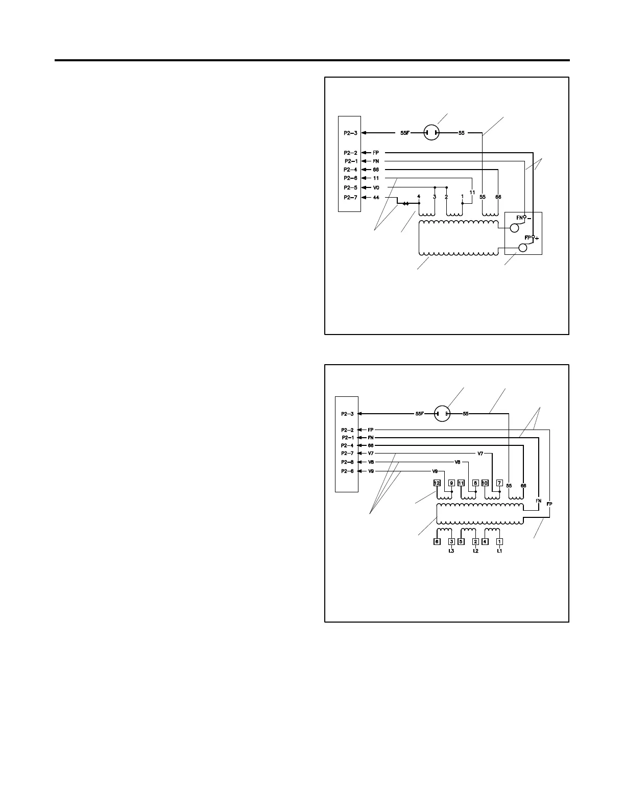
6.1 Theory of Operation
The generator set utilizes a rotating-field alternator to
produce AC voltage. See Figure 6-1 and Figure 6-2.
Refer to Section 8 for the complete generator set
schematics.
When the controller receives a start signal, it energizes
leads FP and 71. FP energizes the rotor field and lead
71 energizes the crank relay P16. The field current
generates a magnetic field that produces AC voltage
when it rotates. The controller monitors this AC voltage
to determine the engine speed. When the controller
senses cranking speed, run relay P17 is energized and
the engine is permitted to start. When the engine speed
reaches about 750 RPM, the alternator produces
sufficient voltage to self-excite. The controller drops
power to lead 71, ending the start sequence. (See
Section 5.2 for a step-by-step engine start sequence.)
When self-excited, the alternator field is energized by
voltage produced in the auxiliary windings, which are
designed solely to provide current to the alternator field.
This current is controlled by the generator controller to
maintain output voltage at the generator’s rated level
(more field current is required as the load on the
generator increases).
Note: The controller does not excite the field during the
warmup or cooldown portion of the cycle
exercise. The field is also disabled during
cooldown and fault cooldown (occurs after
certain faults prior to shutting down).
The controller monitors the generator output voltage
through leads 11 and 44 (single-phase) or leads V7, V8,
and V9 (three-phase 14/20RESA, 20RESC). It receives
a speed signal and power for exciting the field from the
auxiliary windings 55 and 66 and supplies current to the
alternator field through outputs FP and FN.
1. Circuit breaker
(20 amps)
2. Power lead 55
3. Excitation to rotor
4. Brushes
5. Main field (rotor)
6. Stator windings
7. Sensing leads 11 --44
RDC2
Controller
6
4
2
7
5
adv8706
1
3
Figure 6-1 Single-Phase Alternator Schematic
1. Circuit breaker
(20 amps)
2. Power lead 55
3. Excitation to rotor
4. Brushes
5. Main field (rotor)
6. Stator windings
7. Sensing leads
V7, V8, V9
3
adv8706
RDC2
Controller
1
2
7
6
5
4
Figure 6-2 Three-Phase Alternator Schematic,
(14/20RESA, 20RESC)

 Loading...


