EasyManua.ls Logo

Kohler 14RESA User Manual

Kohler 14RESA
172 pages
To Next Page IconTo Next Page
To Previous Page IconTo Previous Page
Page #23 background imageLoading...
Page #23 background image
TP-6805 8/15 23Section 2 Scheduled Maintenance
e. Clean the area around the dipstick and oil fill
cap.
f. Remove the cap from the oil drain hose and
lower the hose into an oil collection container.
g. Open the oil drain valve on the engine.
h. Remove the dipstick and oil fill cap. Allow time
for the engine oil to drain completely.
i. Close the oil drain valve. Replace the cap on
the oil drain hose. Replace the oil drain hose in
its retaining clip.
j. Replace the dipstick.
2. Replace the oil filter.
a. Clean the area around the oil filter. Remove the
oil filter by rotating it counterclockwise with an
oil filter wrench.
b. Clean the gasket sealing surface of the oil filter
adapter.
c. Apply a light coat of clean oil to the rubber seal
of the new oil filter.
d. Install the new oil filter following the instructions
provided with the filter.
3. Fill with oil.
a. Fill the engine to the F mark on the dipstick.
Section 2.2.3, Engine Oil Recommendation,
for oil selection. See Figure 2-3 for the engine
oil capacity.
b. Reinstall the dipstick and the oil fill cap.
c. Reconnect the generator set engine starting
battery, negative (--) lead last.
d. Reconnect utility power to the generator set.
e. Press the RUN button to start and run the
generator set for a minute to allow the oil
pressure to reach operating range.
f. Stop the generator set, wait 1 minute, and then
recheck the oil level. Add oil to bring the level
up to the F mark on the dipstick.
4. Check for leaks.
a. Check for oil leaks.
b. Fix leaks and recheck the oil level.
c. Reinstall the housing side panel.
2.2.5 Oil Cool er, 14kW Mo dels
Inspect and clean the oil cooler at the intervals shown in
the Service Schedule. The oil cooler must be kept free
of debris.
Remove the front enclosure panel to access the oil
cooler. See Section 7.2 for instructions to remove the
front panel.
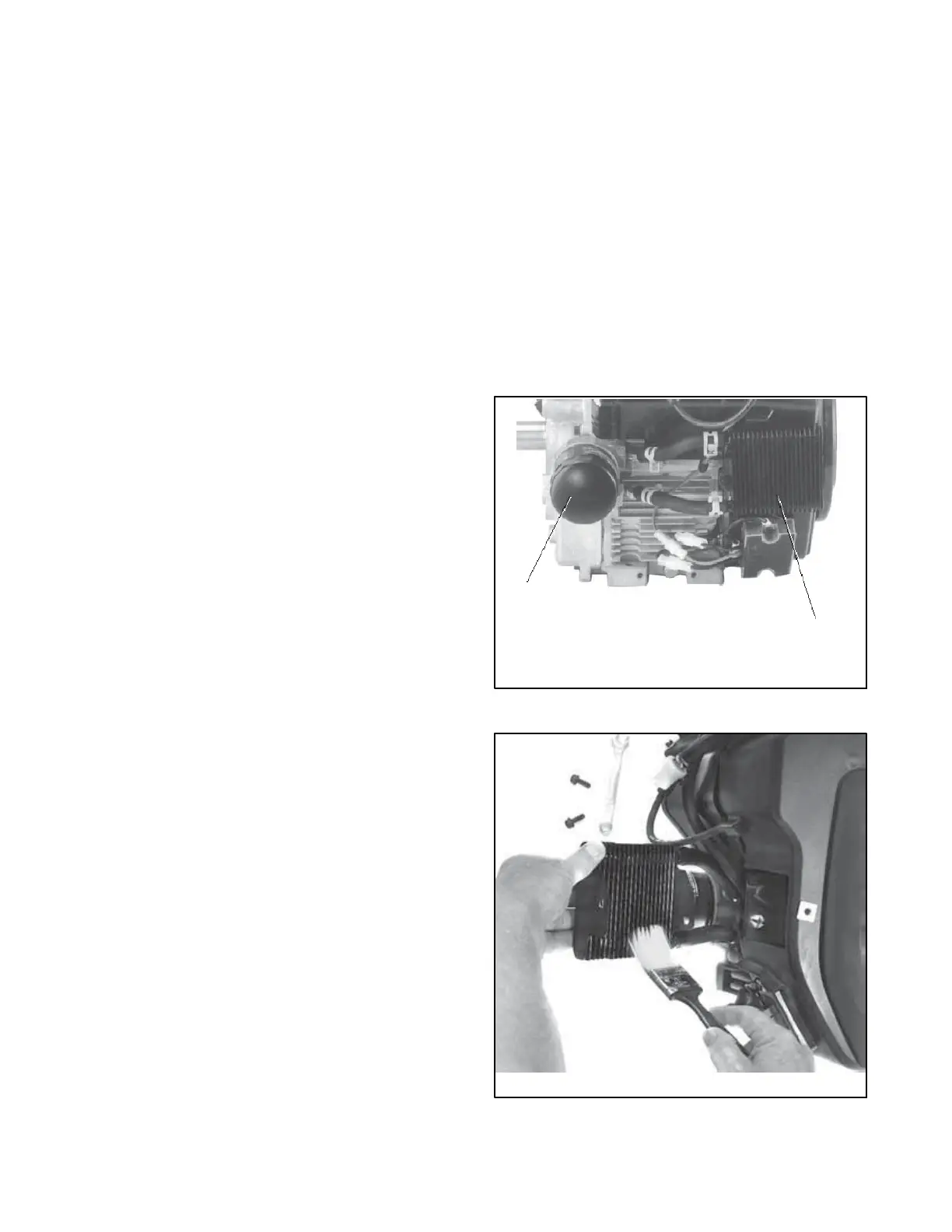
See Figure 2-4 for the oil cooler location. Clean the
outside of the oil cooler with a brush or compressed air.
If it is necessary to clean the back of the oil cooler,
remove the two screws holding the oil cooler unit to the
blower housing. Tilt the cooler and clean with a brush or
compressed air as shown in Figure 2-5. After cleaning,
reinstall the oil cooler and secure with the mounting
screws.
2
24 590 01 -- A
1. Oil filter
2. Oil cooler
1
Figure 2-4 Oil Cooler Location, 14 kW Models
24 590 01 -- A
Figure 2-5 Cleaning the Oil Cooler

Table of Contents

Other manuals for Kohler 14RESA

Questions and Answers:

Kohler 14RESA Specifications

General IconGeneral
Voltage120/240V
Frequency60 Hz
Fuel TypeGasoline
EngineKohler
PhaseSingle Phase
Starting SystemElectric
Warranty3 years limited

Summary

Service

Safety Precautions and Instructions

Accidental Starting

Details hazards and procedures to prevent accidental generator starting.

Battery Safety

Covers safety precautions for handling batteries, acid, and gases.

Engine Backfire and Fuel System Safety

Warns about fire hazards from engine backfire and fuel leaks.

Exhaust System and Carbon Monoxide Safety

Addresses carbon monoxide hazards and exhaust system integrity.

Hazardous Voltage, Moving Parts, and Fuel System Safety

Highlights dangers of hazardous voltage, moving parts, and fuel system safety.

Heavy Equipment and Hot Parts Safety

Covers safety for lifting equipment and hot engine/exhaust components.

Service Assistance

Section 1 Specifications

Section 2 Scheduled Maintenance

Accidental Starting and Hazardous Voltage Precautions

Details safety procedures for accidental starting and hazardous voltage.

Service Schedule and Routine Maintenance

Outlines maintenance tasks, frequency, and routine service based on operating conditions.

Service Schedule Table

A table detailing maintenance tasks, frequency, and corresponding sections.

Battery Maintenance and Cleaning

Provides general information, maintenance, and cleaning instructions for the battery.

Section 3 Generator Reconnection

Voltage Reconnection Procedures

Explains procedures for reconnecting generator set stator leads for different voltages.

Section 4 Controller

SiteTech Software for Controller Management

Explains the use of SiteTech software for controller configuration and firmware updates.

Controller Parameters Overview

Introduces adjustable parameters and notes on selected settings like temperature and engine speed.

Controller Replacement Procedure

Provides instructions for replacing the RDC2 or DC2 controller, including important notes.

Controller Setup Procedure

Details the procedure for setting controller parameters after installation.

Voltage Calibration Procedures

Explains how to check and adjust voltage calibration using keypad or SiteTech.

Section 5 Troubleshooting

Fuel System Troubleshooting Guide

Guides on troubleshooting common fuel system problems related to pressure and regulator function.

Troubleshooting Engine Hunting in 20 kW Models

Provides a sequence to diagnose and resolve engine hunting issues.

Fault Messages and Overload Shutdowns

Lists fault messages, their descriptions, and recommended checks, including overload conditions.

Fault Messages: Battery, Timing, and Speed Issues

Lists fault messages related to battery, timing, speed, and thermostat issues.

Troubleshooting Paralleling Faults and Events

Lists warning messages and events related to paralleling systems.

Troubleshooting Chart

A reference table for troubleshooting individual problems, causes, tests, and corrective actions.

Controller Troubleshooting Guide

Provides a table for troubleshooting controller issues like display problems and communication loss.

Load Management Troubleshooting

Guides on troubleshooting issues with load management devices and controller recognition.

Section 6 Component Testing and Adjustment

Alternator Excitation Theory and Procedures

Covers alternator excitation, including no/low voltage, erratic regulation, and separate excitation.

Voltage Adjustments and Regulator Settings

Explains how to adjust voltage and configure voltage regulator settings.

Fault Shutdown Tests

Verifies the operation of overspeed, overcrank, and low oil pressure shutdowns.

Section 7 Disassembly/Reassembly

Safety Precautions for Disassembly

Highlights critical safety warnings for disassembly procedures.

Section 7 Reassembly

Section 8 Wiring Diagrams

Related product manuals