TP-6805 8/15 99Section 6 Component Testing and Adjustment
6.5 Slip Rings
Slip rings acquire a glossy brown finish in normal
operation. Do not attempt to maintain a bright,
newly-machined appearance on the slip rings. Cleaning
with a dry, lint-free cloth is usually sufficient. Use very
fine sandpaper (#00) and apply light pressure to remove
roughness. Do not use emery or carborundum paper or
cloth. Clean all carbon dust from the generator after
sanding the slip rings. If the rings are b lack or pitted,
remove the r otor and use a lathe to remove some of the
slip ring surface material.
6.6 Brushes
The brushes transfer current to the slip rings. The
brushes should last the life of the generator. However,
abrasive dust on the slip ring can shorten the life of the
brushes.
Excessive arcing at the brushes could damage the
controller. Weak springs, damaged slip rings, sticking
brushes, a loose brush holder, or poor brush contact
causes arcing.
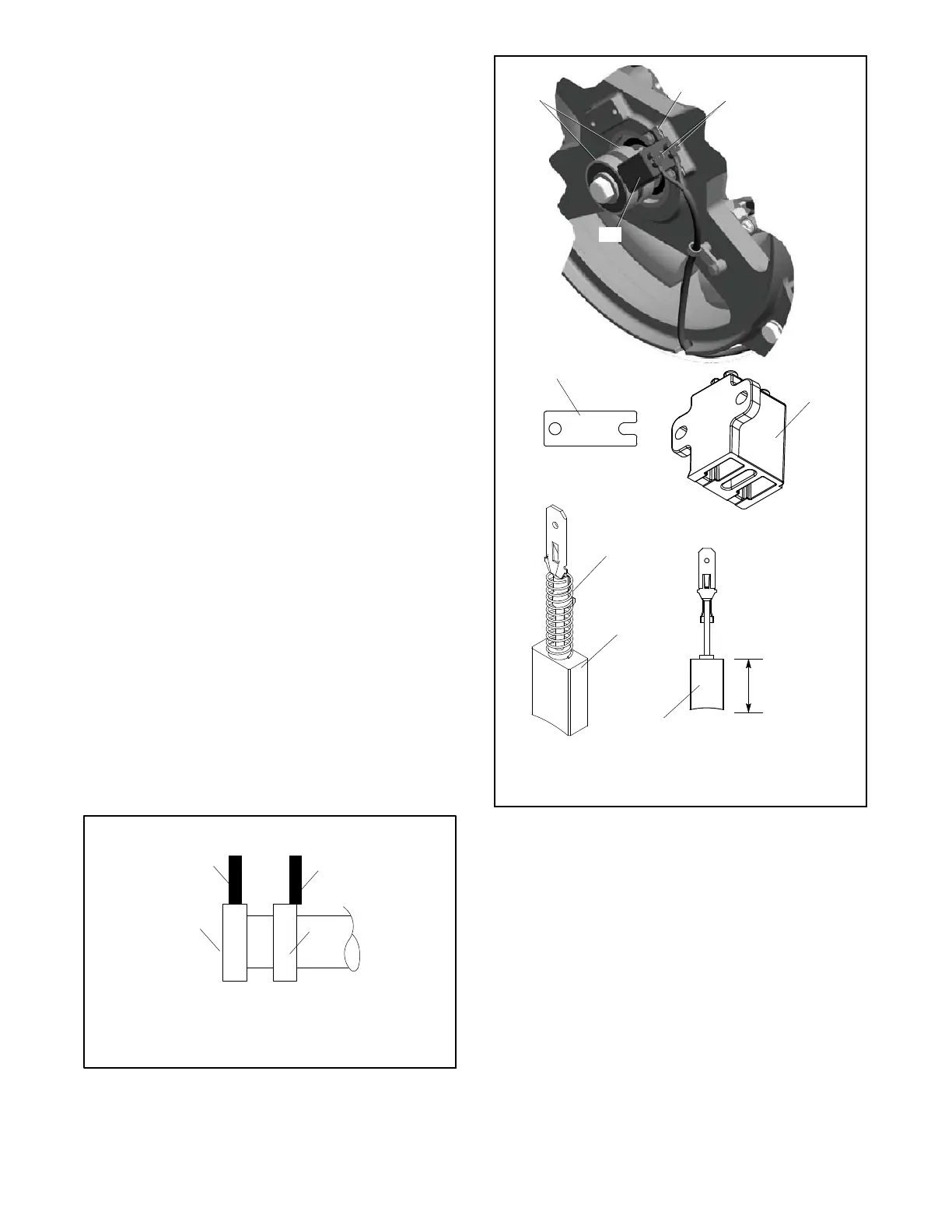
The brush holder assembly is illustrated in Figure 6-11.
The brushes must be free to move within the holder and
be held in contact with the slip rings by the springs.
When correctly positioned, spring pressure on the brush
surface causes the brush to wear evenly. The entire
brush must ride on the ring or arcing occurs and causes
burned rings or voltage regulator failure. Figure 6-10
shows the correct positioning of the brushes. Add or
remove shims as necessary to center the brushes on the
slip rings. Replace the brushes if they show uneven
wear or are worn to one half their original length.
Check the resistance through the brushes. Resistance
through the brushes should be low, 0.1--0.2 ohms
without meter lead resistance.
1. Correctly positioned brush
2. Incorrectly positioned brush
3. Slip rings
TP5867
Side View
1
2
3
3
Correct Incorrect
Figure 6-10 Brush Position
1
1. Brush(es)
2. Brush holder
3. Slip rings
4. Shim
5. Spring
GM80980
GM80981
Length New
19.0 mm
(0.75 in.)
Spring Not
Shown
5
1
1
GM80982
GM62996
2
4
3
4
2
Figure 6-11 Brush Assembly

 Loading...


