TP-6805 8/1564 Section 5 Troubleshooting
D Inadequate fuel supply. Check for damaged
primary or secondary fuel regulators, loose
connections to the fuel solenoid valve, a damaged or
closed fuel shutoff valve, an empty LP fuel tank, or
other problems with the fuel supply. Check the fuel
supply pressure to the generator set. See
Section 6.11, Fuel Systems.
D Fault shutdown. Check for a fault message on the
controller display. Section 5.11 describes the warning
and shutdown fault messages. If a fault message is
displayed, identify and correct the cause of the fault
condition. Then press the OFF button on the
controller to clear the fault.
D Incorrect controller settings. Always check the
controller settings before replacing the controller.
See Section 4.4.1 for controller settings. Refer to the
operation manual for instructions to check and
change the controller settings from the controller
keypad, or use a personal computer and Kohlerr
SiteTecht software.
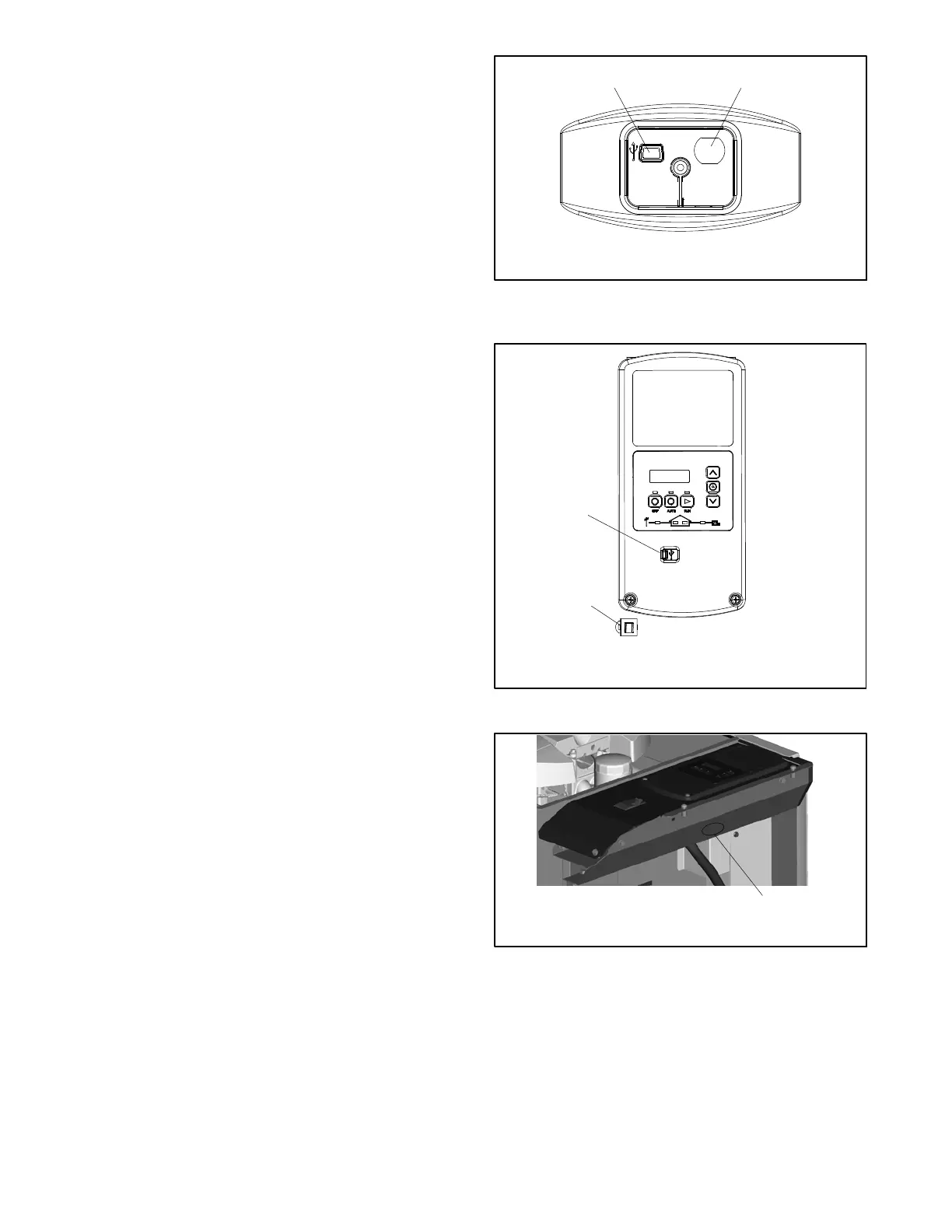
5.4 USB Port and Auxiliary
Winding Mini-Breaker
On original RDC2/DC2 controllers, the USB port and
alternator winding mini circuit breaker are located in the
service access area as shown in Figure 5-1.
Revised controllers have the USB port located under a
small rubber cover as shown in Figure 5-2. The
alternator winding circuit breaker may be located as
shown in Figure 5-2 or Figure 5-3. If an original (green
board) controller has been replaced with a revised (red
board) controller, the circuit breaker may be located
inside the controller trough, under the controller. See
Section 4.6 and Figure 4-13.
A personal computer (laptop) with Kohlerr SiteTecht
software can be used to view the event history and
adjust controller settings. Use a USB cable with a mini-B
connector to connect the controller’s USB port to your
PC. Some settings can be changed from the controller
keypad. All other adjustable settings require a personal
computer (laptop) with Kohlerr SiteTecht software for
changes. Section 4.4 lists controller settings.
See TP-6701, SiteTecht Software Operation Manual,
for software operation instructions.
1. USB port (for service)
2. Alternator winding circuit breaker
1
2
Figure 5-1 Controller Service Access (cover
removed)
1. USB port
2. Auxiliary winding mini-breaker located near the controller
1
GM90304
2
Figure 5-2 Revised Controller and Mini-Breaker
1
1. Alternate mini-breaker location (access through air intake
area)
Figure 5-3 Alternate Location, Auxiliary Winding
Mini-Breaker

 Loading...


