TP-6519 8/17 15Section 1 Specifications
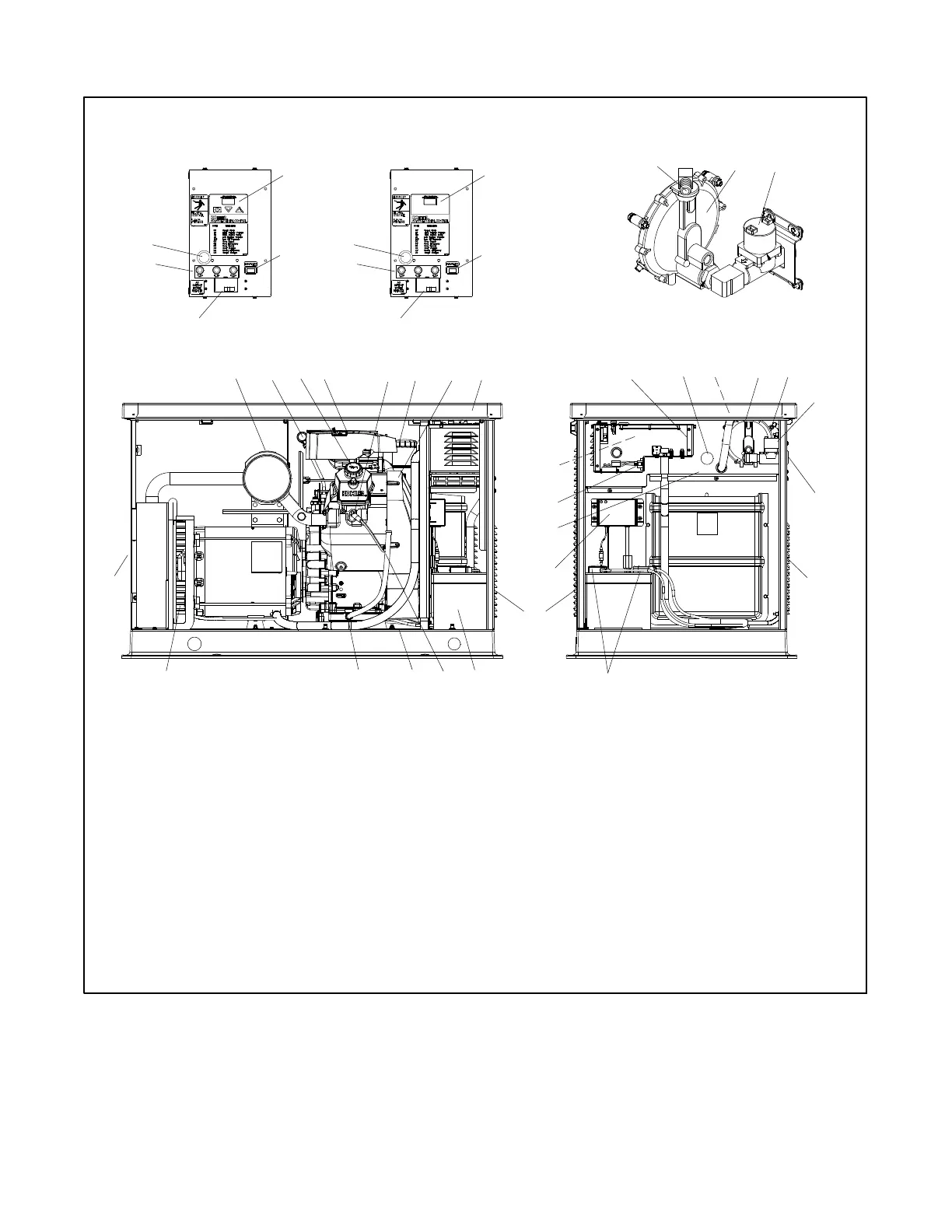
1.7 Service Views
12 5422
17
6
3
14
27
18
21
1516
25
ADV-7341A-B
11
28
26
10
19
23
29
31
Control detail, top view
8
12
7
13
1. Muffler
2. Oil check
3. Oil fill
4. Air cleaner
5. Spark plug locations (both sides)
6. Oil filter
7. Oil cooler location
8. ADC-RES Advanced Digital Control user interface
9. DC-RET control user interface
10. Generator set master switch (RUN-OFF/RESET-AUTO)
11. Line circuit breaker
12. Fuses
13. RS-232 connector (for application program updates)
14. Engine starting battery location (battery purchased separately)
15. Oil drain hose
16. Nameplate location (on base)
17. Oil drain valve
18. Exhaust outlet
19. Relay board location (optional)
20. Carburetor heater access opening
21. LP fuel orifice location (inside hose fitting)
22. Gas regulator assembly
23. DSAI leads
24. Fuel solenoid valve
25. Fuel inlet
26. Air intake
27. Battery cables
28. Battery charger
29. Field-connection terminal block location (RES models)
30. 120 VAC receptacles for battery charger and optional
carburetor heater
31. Field connections inside junction box if optional
terminal block is not used
See control
detail
20
30
24
26
26
Fuel regulator and valve detail
21
24
22
11
10
9
12
13
ADC-RES DC-RET
Figure 1-1 Generator Set Service View
 Loading...


