TP-6519 8/17 41Section 4 Controller
4.5 Controller Configuration and
Adjustment, ADC-RES
The first step in troubleshooting the controller is to verify
that the c ontroller is correctly configured for the
generator set. The ADC-RES controller’s configuration
modes allow selection of the system voltage and
frequency, generator set configuration (marine, mobile,
or standby), and the communication parameter. Follow
the instructions in the generator set installation manual
to check the controller settings and change them, if
necessary.
4.5.1 Controller Configuration
The controller configuration for each generator model is
set a t the factory. If the controller is replaced, check the
configuration of the new controller and change the
settings, if necessary. Follow the instructions in the
generator set installation manual to check controller
settings and change them if necessary.
4.5.2 Controller Time Out
The controller will automatically exit the configuration
mode without saving any changes after about 1 minute
if no buttons are pressed. Start the configuration
procedure again from the beginning if the controller
exits the configuration mode before the settings have
been saved.
Changes in voltage and speed adjustments are also lost
if they are not saved before the generator set shuts
down. The generator set continues to run with the new
settings until it shuts down but then reverts to the
previous settings at the next startup. Be sure to save
your changes immediately after making adjustments.
4.5.3 Controller Application Program
Version Number
The ADC-RES application program version number is
displayed on the LED screen during the key sequence
to enter the configuration mode. Hold the Select button
and move the generator set master switch to the RUN
position. After about 5 seconds, the application
program version number will be displayed on the
controller display. For example, 01.10 will be displayed
for program version 1.10.
The DC-RET application program version number is
displayed during the first 2 seconds of the crank cycle.
4.5.4 Voltage and Frequency
Adjustments
Voltage and/or frequency adjustments may be required
after controller replacement or other service
procedures. See Section 5.8 for instructions to adjust
the generator set output voltage and frequency using
the ADC-RES.
The generator set must be running during these
adjustments. Use a multimeter to measure generator
set output voltage and frequency during adjustments.
Refer to Sections 5.8, Voltage Adjustment, and 5.9.5,
Frequency Adjustment, for instructions to measure and
adjust the output voltage and frequency.
Note: Be sure to save your settings before exiting the
configuration mode. The controller reverts to the
last saved settings when the master switch is
moved to the OFF/RESET position.
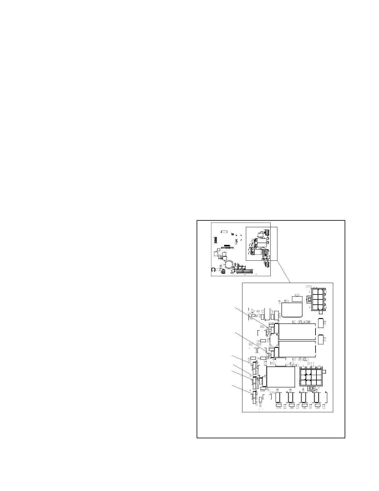
4.6 Controller Relays
The K1 flash, K2 fuel (run), and K3 crank relays are
located on the controller’s logic board. An LED is
associated with each relay. See Figure 4-8.
1. LED1 Flash (K1)
2. LED2 Fuel (K2)
3. LED3 Crank (K3)
4. LED4 Fault
5. LED5 SP2
6. LED6 SP1
1
GM49103
2
3
4
5
6
Figure 4-8 Relays and LEDs on Controller Logic
Board
 Loading...


