TP-6519 8/1742 Section 4 Controller
The LED indicates power to the corresponding relay. If
the LED is illuminated but the relay is not activated, the
relayisfaulty.
The individual relays are not replaceable. If one or more
relays are faulty, replace logic board.
LED 4 lights to indicate a fault condition. See
Section 4.4, Faults.
The controller board is protected by a 10-amp fuse (F2)
located on the controller. If the fuse blows repeatedly,
disconnect the board loads one at a time to identify the
cause of the blown fuse:
D Lead 70C at the fuel valve
D Lead IGN at the ignition module
D Lead 71A at the starter relay
D Leads FP and FN at the rotor
Repair or replace the component causing the blown
fuse.
If fuse continues to blow and disconnecting
components did not identify the cause, remove the
leads from the P14 connector using a pin pusher. If
replacing the leads does not solve the problem, replace
the controller logic board.
4.7 Optional Relay Board
The generator set may be equipped with an optional
relay board, which contains the K1 common fault relay
and K4 auxiliary run relay. See Figure 4-9 for the relay
board location inside the controller junction box.
GM53102
1
2
3
3
1. Relay board GM51403
2. Controller circuit board location
3. Cover screws (qty. 4)
Figure 4-9 Relay Board Location
(inside controller junction box)
Troubleshooting
First check for loose connections. Check the relay
board harness connections to the relay board, control
board, and engine harness. See Figure 4-10,
Figure 4-11, and Figure 4-12.
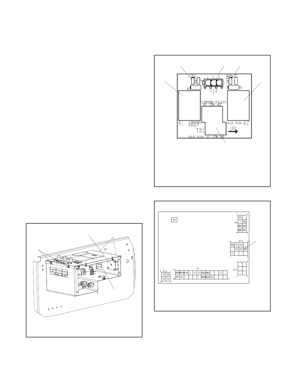
5
1. K1 common fault (CF) relay
2. LED1 (for K1 CF relay)
3. Connect P14 from RIB harness GM52639 to P14 on the
relay board
4. LED2 ( for K2 aux. run relay)
5. K2 auxiliary run relay
6. Connect customer equipment to TB1, 14 AWG max.
2
1
6
3
GM51403
4
Figure 4-10 Optional Relay Board
from GM52541
1. Disconnect engine harness from controller circuit board at
P11. Connect relay board harness GM52639 to P11.
1
Figure 4-11 Connection to Controller C ircuit Board
 Loading...


