TP-6519 8/1768 Section 5 Component Testing and Adjustment
Remove the LOP switch and install an oil pressure
gauge to verify that the engine oil pressure is within the
range specified in Section 1, Specifications, before
testing or replacing the LOP switch. To test the LOP
switch, reinstall the switch and start the generator set. If
the unit shuts down, disconnect lead 13 from the LOP
switch and reset the controller. Restart the generator
set and verify that it does not shut down. A successful
restart indicates a faulty LOP switch. Replace switch.
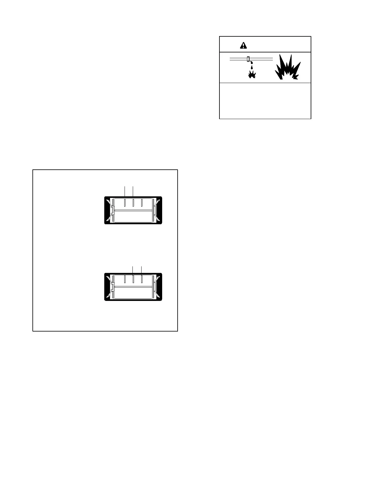
5.11 Generator Set Master Switch
The generator set master switch is a three-position
(RUN\OFF/RESET\AUTO) rocker switch. The leads
connecting to the master switch are labeled RUN,
VBAT, and AUTO. Check that the three connectors are
connected to the terminals on the back of the switch as
shown in Figure 5-31. Be careful not to reverse the
RUN and AUTO leads.
tp6196
Master Switch in
RUN Position
Master Switch in
AUTO Position
Zero ohms (continuity) across
RUN and VBAT terminals
Zero ohms (continuity) across
VBAT and AUTO terminals
AUTO
RUN
VBAT
AUTO
RUN
VBAT
(back view)
Figure 5-31 Generator Set Master Switch Continuity
Checks
5.12 Fuel Systems
Explosive fuel vapors.
Can cause severe injury or death.
Use extreme care when handling,
storing, and using fuels.
WARNING
The fuel supplier provides and maintains manual
shut-off valves and the primary regulator. See the
generator set installation manual for fuel pipe size
recommendations. Verify that the fuel system capacity
is adequate to supply the generator set plus all other gas
appliances.
A factory-installed secondary regulator and 12 VDC
solenoid valve are located in the front inlet air
compartment. The controller energizes the fuel
solenoid valve to open at startup and deenergizes the
valve to close at shutdown. The secondary fuel
regulator reduces fuel pressure for delivery to the fuel
block. The fuel flows from the fuel block to the
carburetor in a gaseous state. The carburetor mixes the
fuel with intake air for consumption by the engine.
Refer to the troubleshooting instructions in Section 3,
Troubleshooting, to identify generator set operation
problems that may be caused by an inadequate fuel
supply, incorrect adjustments, or damaged fuel system
components. Then use the instructions in this section to
check fuel system components.
5.12.1 Fuel Solenoid Valve
A solenoid valve upstream of the regulator and the
flexible fuel connector provides automatic fuel on/off
control. The engine starting battery powers the solenoid
valve and the engine starting controls open the valve
when the engine cranks or runs.
Gas Valve Operation Test Procedure
1. Disconnect the positive ( +) battery lead from the
gas valve terminal.
2. Apply 12 VDC to the gas valve terminal and listen
for an audible click, indicating that the valve
actuates.
3. Replace the gas valve if it does not actuate in
step 2.
 Loading...


